MAX32600 User’s Guide
Analog Front End
8.5 LED
8.5.2.9
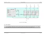
3x3 LED Matrix Configuration
Figure 8.19: 3x3 LED Matrix Configuration
In LED matrix configuration, LED capable I/Os are used at the bottom of the matrix structure, and simple I/Os for the top sides. For proper operation, the top and
bottom I/Os must be switched in a time multiplexed manner.
The simplest method of control enables only one LED at a time, but always retains current in the sense resistor. The LEDs are controlled by a combination of the top
and bottom drivers and lit in sequence.
The LED capable drivers run at the refresh rate with a 1/3 duty cycle. The top drivers run at three times faster than the refresh frequency with a 1/3 duty cycle. The
average brightness is 1/9 the on brightness—as the current is time multiplexed into the nine LEDs. The low average current means that either the peak current needs
to be brighter (in this case the bottom drivers run at the refresh rate with a 1/3 duty cycle, and the top drivers must be able to support this) or the low brightness is
acceptable.
LED brightness can be addressed in a number of ways. Multiple LEDs could be enabled simultaneously, thus extending the duty cycle. This encounters difficulty,
however, because the diodes will tend to split the current unevenly, leading to brightness variations. An alternate way to approach LED brightness is to keep the
anode common to all diodes on simultaneously and switching the cathode. This option delivers favorable results because the NMOS switch device operates in
saturation and has good output conductance. It must be considered, though, that the pullup device is substantially weaker than the pulldown, so the sum of the
currents into the row is limited to
∼
25mA unless the pullups are operated in parallel. Brightness of individual diodes can be adjusted by fine-tuning the duty cycle.
Rev.1.3 April 2015
Maxim Integrated
Page 481

