MAX32600 User’s Guide
Analog Front End
8.3 ADC
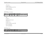
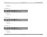
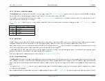
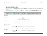
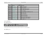
Interrupt flags are in the ADC_INTR register and include:
•
- Set when the ADC FIFO exceeds the almost full threshold.
•
- Underflow condition occurred.
•
- Overflow condition occurred. This indicates the ADC FIFO is full and samples are being overwritten.
•
- Interrupt flag set when the FIFO reaches three-quarters full.
•
- Interrupt flag set when the FIFO reaches half full.
•
- Interrupt flag set when the FIFO reaches one-quarter full.
8.3.4.7
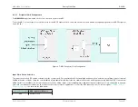
Programmable Gain Amplifier
The
MAX32600
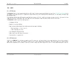
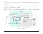
ADC signal chain includes a Programmable Gain Amplifier (PGA) between the Input Mux and the ADC. The PGA takes the outputs from the Input
Mux and amplifies it prior to processing by the ADC. This improves the signal-to-noise ratio of low amplitude signals. Bypassing the PGA is supported and results in
higher sample rates for the ADC. If enabled, the PGA supports gain settings of 1X, 2X, 4X, and 8X.
Note
Optimal SNR and THD are generally achieved by bypassing the PGA and sending the input signal directly to the ADC. However, at full sampling rate,
the acquisition time of the PGA is much longer than that of the ADC (i.e., 1.5us vs. 125ns); this can allow for more complete settling of the measured
signal if the input source impedance is too high.
PGA Configuration
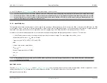
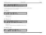
The PGA can be enabled or bypassed as required by the application. The register field
is set to 1 to bypass the PGA. The default
is for the PGA to be enabled and in the signal chain.
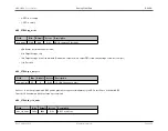
The Gain setting for the PGA is controlled via the
register field:
• 00b = 1X
• 01b = 2X
• 10b = 4X
• 11b = 8X
Rev.1.3 April 2015
Maxim Integrated
Page 415

