


MAX32600 User’s Guide
Pin Configurations, Packages, and Special Function Multiplexing
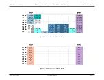
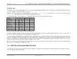
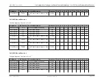
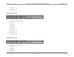
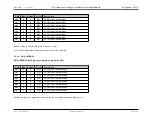
5.5 Registers (GPIO)
• 0: Port pin is not available for GPIO use.
• 1: Port pin is available for GPIO use.
Note
All GPIO registers of this type (GPIO_FREE_Px) follow this same format.
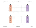
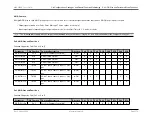
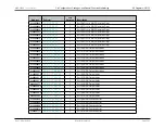
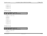
5.5.1.2
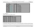
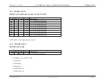
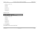
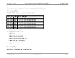
GPIO_OUT_MODE_Pn
GPIO_OUT_MODE_Pn.[pin0, pin1, pin2, pin3, pin4, pin5, pin6, pin7]
Field
Bits
Default
Access
Description
pin0
3:0
0000b
R/W
Pn.0 Output Drive Mode
pin1
7:4
0000b
R/W
Pn.1 Output Drive Mode
pin2
11:8
0000b
R/W
Pn.2 Output Drive Mode
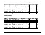
pin3
15:12
0000b
R/W
Pn.3 Output Drive Mode
pin4
19:16
0000b
R/W
Pn.4 Output Drive Mode
pin5
23:20
0000b
R/W
Pn.5 Output Drive Mode
pin6
27:24
0000b
R/W
Pn.6 Output Drive Mode
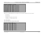
pin7
31:28
0000b
R/W
Pn.7 Output Drive Mode
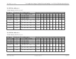
• 0: High impedance w/optional weak pullup
• 1: Open drain
• 2: Open drain w/weak pullup
• 3: High impedance
• 4: Normal drive, High impedance
• 5: Normal drive, Drive high/low
• 6: Slow drive, High impedance
• 7: Slow drive, Drive high/low
• 8: Fast drive, High impedance
• 9: Fast drive, Drive high/low
Rev.1.3 April 2015
Maxim Integrated
Page 184