MAX32600 User’s Guide
Communication Peripherals
7.3 UART
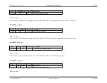
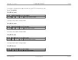
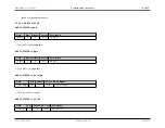
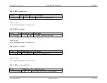
Registers for UART1
Address
Register
Details
0x40039000
UART Control Register
0x40039004
UART Status Register
0x40039008
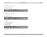
Interrupt Enable/Disable Controls
0x4003900C
Interrupt Flags
0x40039010
Baud Rate Setting (Integer Portion)
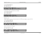
0x40039014
Baud Rate Setting (Div 128 Decimal Portion)
0x40039018
TX FIFO Output End (read-only)
0x4003901C
Hardware Flow Control Register
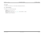
0x40039020
Write to load TX FIFO, Read to unload RX FIFO
7.3.4
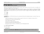
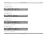
UART Clock Selection and Clock Gating
The UARTs in the
MAX32600
use the System Core Clock. To enable a specific UART, it is necessary enable clocks for the port. In addition, the baud clock enable
bit must be set in
to allow baud clock generation (required for transmit only). There are two options that will ensure the UART clocks are
enabled: Dynamic Clock Gating and turning the clock on without clock gating. To enable the UART clocks for a given port, the fields
or
CLKMAN_CLK_GATE_CTRL0.uart1_clk_gater
should be set as shown in the table below.
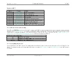
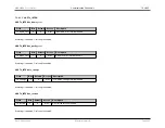
UART Clock Control (2b)
Setting
00b
Clock off
- UART disabled
01b
Dynamic Clock Gating Enabled
- UART clock active only when used
10b or 11b
Clock on
- UART enabled at all times
7.3.5
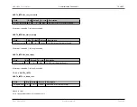
Format and Baud Rate Selection
The overall baud rate for the UART is based on the nominal peripheral clock frequency, which is derived from the main system clock as controlled by the Clock
Manager. To set the baud rate value, write the appropriate divider values to the registers
and
for the UART instance to
be configured.
Rev.1.3 April 2015
Maxim Integrated
Page 286


