MAX32600 User’s Guide
Analog Front End
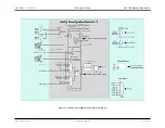
8.2 AFE Reconfiguration Matrix
Analog
Reconfiguration
Matrix
DACOUT
Op Amp Positive
Input
Op Amp Negative
Input
Op Amp Output
LED Observe Port
Input
SCM Pin
SNO Pin
3
SNO1
IND+
IND-
OUTD
1
SCM3
SNO3
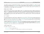
Within each analog reconfiguration matrix, there are six multiplexers and one switch that control the op amp and comparator inputs as well as the SPST switch and
op amp negative input external pins. Note that external pins can be both inputs and outputs; care must be taken in programming the matrix to avoid undesired loops
or short circuits.
8.2.1.1
DAC
The four DAC inputs—dac0, dac1 (previously multiplexed at the matrix top-level) and DAC2p, DAC3p (directly from the 8-bit DACs)—drive a 4:1 mux that outputs
the dac_orN signal (where N=A,B,C,D depending on the particular analog reconfiguration matrix). The dac_orN signal can be brought out to the SPST external pin
via the
, and
register fields and is also used as an input to the op amp positive input mux and op amp negative
external pin mux.
8.2.1.2
Op Amps
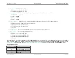
The op amp positive input is driven by a 4:1 mux selecting either the INX+ external pin or the internally derived signals dac_orN and sno_or. A fourth state selects
the dac_orN signal and also sends dac_orN to the INX+ external pin. Note that in this configuration any resistive load on the INX+ external pin will load the DAC
output. All the multiplexers are implemented as analog switches and normally have only one switch active at any moment; in this case, two of the analog switches
are selected so that a three-way connection is possible. The three-way connections only occur with external pin connections for the purpose of internal observability.
The op amp negative input is driven by one of three sources: the INX- external pin, the op amp output OUTX, or the scm_or input. A fourth state selects both scm_or
and the INX- pin.
The op amp negative external pin can be driven by the locally generated dac_orN signal described above, the LED Observe Port input, or both. A fourth state
disconnects the mux (this is denoted as a HiZ signal in the
so that the INX- pin can be driven externally. This is the default condition for the mux. Note that
because of the various mux options, the “op amp negative pin” INX- is not always the negative input to the op amp.
Additionally, there is a ground select switch on each of the op amp positive input external pins INX+ that shorts the pin to V
SS
with an impedance of 30 Ohms when
set to a 1. To choose this option, use register fields
, and
. Note that the op amp positive
input mux must be set appropriately for this to affect the op amp positive input.
Op Amp Control
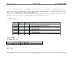
Each op amp has four control signals set by the corresponding AFE control register bits. Bit
controls the power-up of each op amp where X = A, B,
C, or D. This bit must be set for the op amp to operate. If 0, the OUTX output goes into a high-impedance state. The op amp has two independent input stages,
Rev.1.3 April 2015
Maxim Integrated
Page 350


