AT-1
AUTOMATIC TRANSAXLE
C TRANSMISSION/TRANSAXLE
CONTENTS
D
E
F
G
H
I
J
K
L
M
SECTION
A
B
AT
Revision: November 2006
2006 Altima
RE4F04B
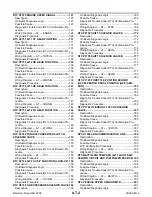
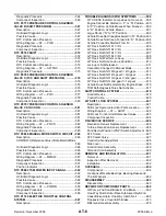
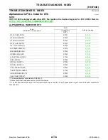
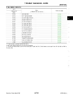
TROUBLE DIAGNOSIS - INDEX ................................ 8
Alphabetical & P No. Index for DTC ......................... 8
PRECAUTIONS ........................................................ 10
Precautions for Supplemental Restraint System
(SRS) “AIR BAG” and “SEAT BELT PRE-TEN-
SIONER” ................................................................ 10
Precautions for On Board Diagnostic (OBD) System
of A/T and Engine .................................................. 10
Precautions ............................................................ 10
Service Notice or Precautions ................................ 12
PREPARATION ......................................................... 14
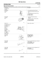
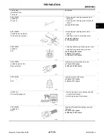
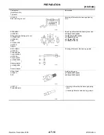
Special Service Tools ............................................. 14
Commercial Service Tools ...................................... 17
A/T FLUID ................................................................. 18
Changing A/T Fluid ................................................ 18
Checking A/T Fluid ................................................. 18
A/T Fluid Cooler Cleaning ...................................... 19
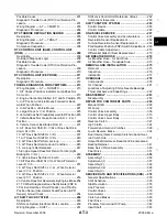
OVERALL SYSTEM ................................................. 23
A/T Electrical Parts Location .................................. 23
Circuit Diagram ...................................................... 24
Cross-sectional View .............................................. 25
Hydraulic Control Circuit ........................................ 26
Shift Mechanism ..................................................... 27
Control System ....................................................... 36
Control Mechanism ................................................ 38
Control Valve .......................................................... 42
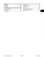
Introduction ............................................................ 44
OBD-II Function for A/T System ............................. 44
One or Two Trip Detection Logic of OBD-II ............ 44
OBD-II Diagnostic Trouble Code (DTC) ................. 44
Malfunction Indicator Lamp (MIL) ........................... 48
CONSULT-II Function (TCM) ................................. 48
Diagnostic Procedure Without CONSULT-II ........... 59
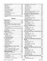
TROUBLE DIAGNOSIS - INTRODUCTION ............. 64
Introduction ............................................................ 64
Work Flow .............................................................. 68
TROUBLE DIAGNOSIS - BASIC INSPECTION ....... 71
A/T Fluid Check ...................................................... 71
A/T Fluid Cooler Cleaning ...................................... 71
Stall Test ................................................................. 74
Line Pressure Test .................................................. 77
Road Test ............................................................... 78
Symptom Chart ....................................................... 93
TCM Terminals and Reference Value ................... 103
CAN Communication ............................................ 106
TROUBLE DIAGNOSIS FOR POWER SUPPLY .... 107
Wiring Diagram — AT — MAIN ............................ 107
Diagnostic Procedure ........................................... 108
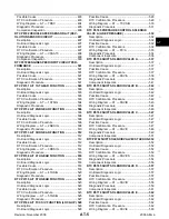
DTC P0705 PARK/NEUTRAL POSITION SWITCH .110
Description ............................................................ 110
On Board Diagnosis Logic .................................... 110
Possible Cause ..................................................... 110
Diagnostic Trouble Code (DTC) Confirmation Pro-
cedure ................................................................... 110
Wiring Diagram — AT — PNP/SW ....................... 112
Diagnostic Procedure ........................................... 113
Description ............................................................ 116
On Board Diagnosis Logic .................................... 116
Possible Cause ..................................................... 116
Diagnostic Trouble Code (DTC) Confirmation Pro-
cedure ................................................................... 116
Wiring Diagram — AT — FTS .............................. 118
Diagnostic Procedure ........................................... 120
Description ............................................................ 122
On Board Diagnosis Logic .................................... 122
Possible Cause ..................................................... 122
Diagnostic Trouble Code (DTC) Confirmation Pro-
cedure ................................................................... 122
Wiring Diagram — AT — VSSA/T ........................ 124
Diagnostic Procedure ........................................... 125


