AT-578
[RE5F22A]
DTC P0795 PRESSURE CONTROL SOLENOID VALVE C (TCC AND SHIFT
PRESSURE)
Revision: November 2006
2006 Altima
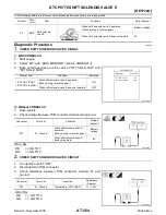
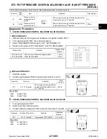
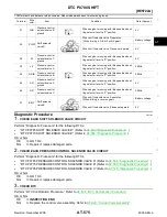
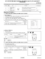
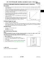
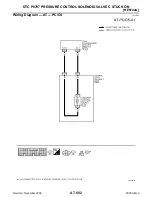
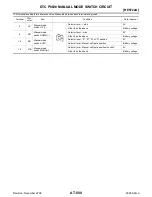
TCM terminals and data are reference value. Measured between each terminal and ground.
Diagnostic Procedure
ECS009HQ
1.
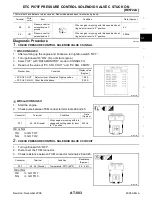
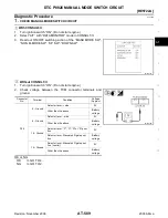
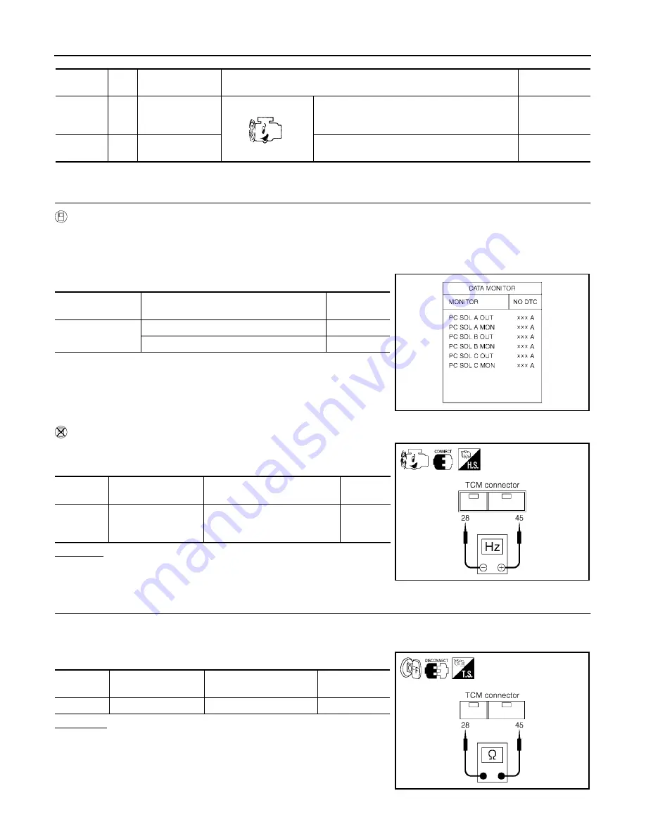
CHECK PRESSURE CONTROL SOLENOID VALVE C SIGNAL
With CONSULT-II
1.
After warming up the engine and transaxle, turn ignition switch “OFF”.
2.
Turn ignition switch “ON”. (Do not start engine.)
3.
Select “A/T” with “DATA MONITOR” mode in CONSULT-II.
4.
Read out the value of “PC SOL C OUT” and “PC SOL C MON”.
Without CONSULT-II
1.
Start the engine.
2.
Check pulse between TCM connector terminals 28 and 45.
OK or NG
OK >> GO
TO
7.
NG
>> GO TO 2.
2.
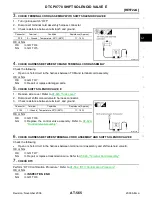
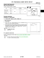
CHECK PRESSURE CONTROL SOLENOID VALVE C CIRCUIT
1.
Turn ignition switch “OFF”.
2.
Disconnect the TCM connector.
3.
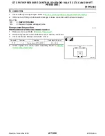
Check resistance between TCM connector terminals 28 and 45.
OK or NG
OK
>> GO TO 7.
NG
>> GO TO 3.
Terminal
Wire
color
Item
Condition
Data (Approx.)
28
W
Pressure control
solenoid valve C
ground
When engine is running with idle speed and set-
ting selector lever to “P” position.
0V
45
OR
Pressure control
solenoid valve C
When engine is running with idle speed and set-
ting selector lever to “P” position.
300Hz
Monitor item
Condition
Display value
(Approx.)
●
PC SOL C OUT
●
PC SOL C MON
Selector lever: Manual shift gate position
1.00 A
Other than the above.
0.20 A
SCIA2907E
Connector
Terminal
Condition
Data
(Approx.)
F57
45 - 28 (Ground)
When engine is running with idle
speed and setting selector lever
to “P” position.
300 Hz
SCIA2914E
Connector
Terminal
Condition
Resistance
(Approx.)
F57
45 - 28 (Ground)
Temperature: 20
°
C (68
°
F)
5.0 - 5.6
Ω
SCIA2915E

