
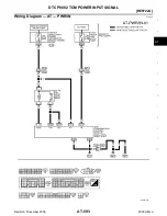

DTC P0882 TCM POWER INPUT SIGNAL
AT-595
[RE5F22A]
D
E
F
G
H
I
J
K
L
M
A
B
AT
Revision: November 2006
2006 Altima
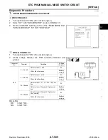
Diagnostic Procedure
ECS009ID
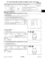
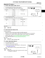
1.
CHECK TCM POWER SOURCE CIRCUIT
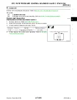
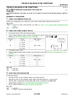
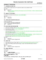
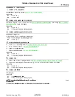
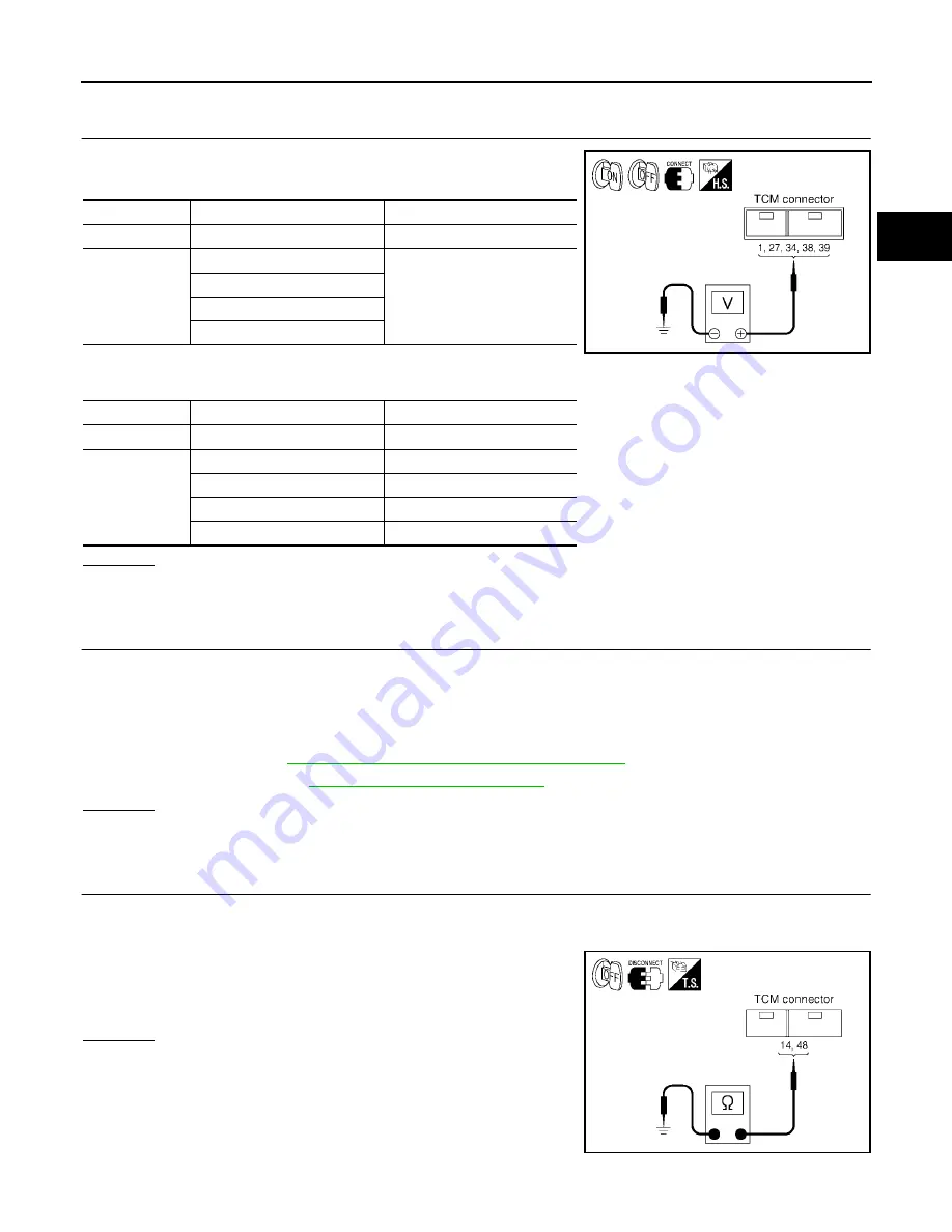
1.
Turn ignition switch “ON”. (Do not start engine.)
2.
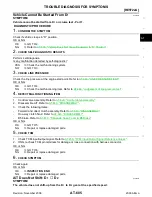
Check voltage between TCM terminals and ground.
3.
Turn ignition switch “OFF”.
4.
Check voltage between TCM terminals and ground.
OK or NG
OK
>> GO TO 3.
NG
>> GO TO 2.
2.
DETECT MALFUNCTIONING ITEM
Check the following:
●
Harness for short or open between battery and TCM terminal 27
●
Harness for short or open between ignition switch and TCM terminals 1, 34, 38 and 39
●
10A fuse [No. 19, located in the fuse block (J/B) or No. 48, located in the IPDM E/R]
●
Ignition switch. Refer to
PG-4, "POWER SUPPLY ROUTING CIRCUIT"
●
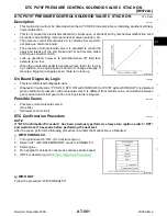
A/T PV IGN relay. Refer to
AT-596, "Component Inspection"
OK or NG
OK
>> GO TO 3.
NG
>> Repair or replace damaged parts.
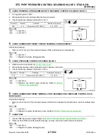
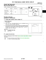
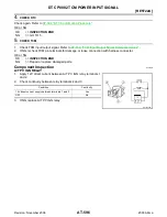
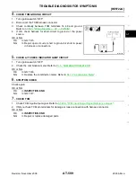
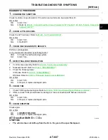
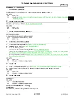
3.
CHECK TCM GROUND CIRCUIT
1.
Turn ignition switch “OFF”.
2.
Disconnect TCM harness connector.
3.
Check continuity between TCM terminals 14, 48 and ground.
If OK, check harness for short to ground and short to power.
OK or NG
OK
>> GO TO 4.
NG
>> Repair open circuit or short to ground or short to power
in harness or connectors.
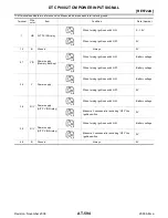
Connector
Terminal Voltage
(Approx.)
F56
1 - Ground
0 - 1.5V
F57
27 - Ground
Battery voltage
34 - Ground
38 - Ground
39 - Ground
Connector
Terminal
Voltage (Approx.)
F56
1 - Ground
0V
F57
27 - Ground
Battery voltage
34 - Ground
0V
38 - Ground
0V
39 - Ground
0V
SCIA2930E
Continuity should exist.
SCIA2933E