TROUBLE DIAGNOSIS - GENERAL DESCRIPTION
AT-105
[RE4F04B]
D
E
F
G
H
I
J
K
L
M
A
B
AT
Revision: November 2006
2006 Altima
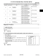
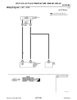
*: These terminals are connected to the ECM.
**: These terminals are connected to the Data link connector.
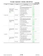
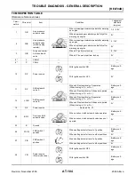
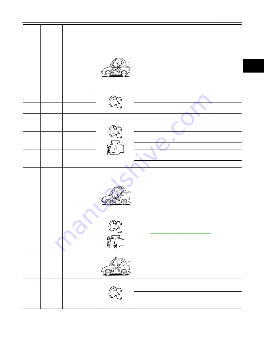
29
W
Revolution sensor
When moving at 20 km/h (12 MPH), use the
CONSULT-II pulse frequency measuring func-
tion.*1
CAUTION:
Connect the diagnosis data link cable to the
vehicle diagnosis connector.
*1: A circuit tester cannot be used to test this
item.
450 Hz
When vehicle is parked.
Under 1.3V or
over 4.5V
30**
BR/Y
Data link connec-
tor (RX)
—
—
31**
LG
Data link connec-
tor (TX)
—
—
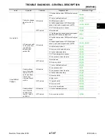
34
G
PNP switch D
position
When setting selector lever to D position.
Battery volt-
age
When setting selector lever to other positions.
0V
35
G/W
PNP switch R
position
When setting selector lever to R position.
Battery volt-
age
When setting selector lever to other positions.
0V
36
R/B
PNP switch P or N
position
When setting selector lever to P or N position.
Battery volt-
age
When setting selector lever to other positions.
0V
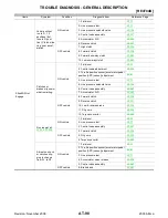
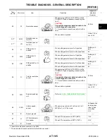
38
G
Turbine revolution
sensor
When moving at 20 km/h (12 MPH), use the
CONSULT-II pulse frequency measuring func-
tion.*1
CAUTION:
Connect the diagnosis data link cable to the
vehicle diagnosis connector.
*1: A circuit tester cannot be used to test this
item.
240 Hz
When vehicle is parked.
Under 1.3V or
over 4.5V
39
W/G
Engine speed sig-
nal
EC-109, "ECM INSPECTION TABLE"
40
PU/R
Vehicle speed
sensor
When moving vehicle at 2 to 3 km/h (1 to 2
MPH) for 1 m (3 ft) or more.
Voltage varies
between less
than 1V and
more than
4.5V
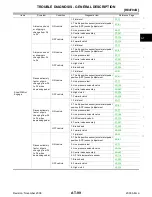
42
B
Sensor ground
—
—
—
47
G
A/T fluid tempera-
ture sensor
When ATF temperature is 20
°
C (68
°
F).
1.5V
When ATF temperature is 80
°
C (176
°
F).
0.5V
48
B
Ground
—
—
—
Termi-
nal No.
Wire color
Item
Condition
Judgement
standard
(Approx.)


