AT-3
D
E
F
G
H
I
J
K
L
M
A
B
AT
Revision: November 2006
2006 Altima
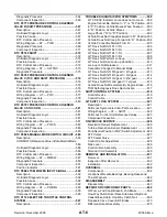
Possible Cause .................................................... 201
Diagnostic Trouble Code (DTC) Confirmation Pro-
cedure .................................................................. 201
Wiring Diagram — AT — VSSMTR ...................... 203
Diagnostic Procedure ........................................... 204
DTC TURBINE REVOLUTION SENSOR ............... 205
Description ........................................................... 205
Wiring Diagram — AT — TRSA/T ........................ 206
Diagnostic Procedure ........................................... 207
Component Inspection ......................................... 208
Description ........................................................... 209
On Board Diagnosis Logic ................................... 209
Possible Cause .................................................... 209
Diagnostic Trouble Code (DTC) Confirmation Pro-
cedure .................................................................. 209
Diagnostic Procedure ........................................... 210
DTC CONTROL UNIT (EEP ROM) ..........................211
Description ............................................................211
Diagnostic Procedure ........................................... 212
TROUBLE DIAGNOSIS FOR SYMPTOMS ............ 213
Wiring Diagram — AT — NONDTC ...................... 213
1. A/T Check (Position) Indicator Lamp Does Not
Come On .............................................................. 217
2. Engine Cannot Be Started In P and N Position . 219
3. In P Position, Vehicle Moves Forward or Back-
ward When Pushed .............................................. 220
4. In N Position, Vehicle Moves ............................ 221
5. Large Shock. N
R Position .......................... 223
6. Vehicle Does Not Creep Backward In R Position
7. Vehicle Does Not Creep Forward in D, 3, 2 or 1
Position ................................................................ 228
8. Vehicle Cannot Be Started From D
..................................................... 234
.......................... 240
12. A/T Does Not Perform Lock-up ...................... 243
13. A/T Does Not Hold Lock-up Condition ........... 245
14. Lock-up Is Not Released ................................ 247
15. Engine Speed Does Not Return To Idle (Light
Braking D
) ................................................ 248
16. Vehicle Does Not Start From D
3 ......................................................... 251
2 Position ............................................ 252
1 Position ............................................ 253
20. Vehicle Does Not Decelerate By Engine Brake
A/T SHIFT LOCK SYSTEM .................................... 260
Description ........................................................... 260
Shift Lock System Electrical Parts Location ......... 260
Wiring Diagram — SHIFT — ................................ 261
Shift Lock Control Unit Reference Values ............ 262
Component Inspection .......................................... 263
SHIFT CONTROL SYSTEM .................................... 265
Control Device ...................................................... 265
Control Cable ........................................................ 266
ON-VEHICLE SERVICE .......................................... 267
Control Valve Assembly and Accumulators .......... 267
Revolution Sensor Replacement .......................... 269
Turbine Revolution Sensor Replacement ............. 269
Park/Neutral Position (PNP) Switch Adjustment .. 269
Control Cable Adjustment ..................................... 270
Differential Side Oil Seal Replacement ................ 270
AIR BREATHER HOSE .......................................... 272
Air Breather Hose - Air Duct Side ......................... 272
Air Breather Hose - Transaxle Side ...................... 273
REMOVAL AND INSTALLATION ........................... 275
Removal ............................................................... 275
Inspection ............................................................. 276
Installation ............................................................ 277
OVERHAUL ............................................................ 278
Components ......................................................... 278
Oil Channel ........................................................... 281
Locations of Adjusting Shims, Needle Bearings,
Thrust Washers and Snap Rings .......................... 282
DISASSEMBLY ....................................................... 283
Disassembly ......................................................... 283
REPAIR FOR COMPONENT PARTS ..................... 299
Manual Shaft ........................................................ 299
Oil Pump ............................................................... 302
Control Valve Assembly ........................................ 306
Control Valve Upper Body .................................... 315
Control Valve Lower Body .................................... 319
Reverse Clutch ..................................................... 321
High Clutch ........................................................... 324
Forward and Overrun Clutches ............................ 328
Low & Reverse Brake ........................................... 334
Rear Internal Gear, Forward Clutch Hub and Over-
run Clutch Hub ...................................................... 337
Output Shaft, Idler Gear, Reduction Pinion Gear and
Bearing Retainer ................................................... 341
Band Servo Piston Assembly ............................... 346
Final Drive ............................................................ 351
ASSEMBLY ............................................................. 356
Assembly (1) ......................................................... 356
Adjustment (1) ...................................................... 357
Assembly (2) ......................................................... 362
Adjustment (2) ...................................................... 369
Assembly (3) ......................................................... 371
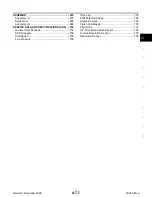
SERVICE DATA AND SPECIFICATIONS (SDS) .... 378
General Specifications .......................................... 378
Shift Schedule ...................................................... 378
Stall Revolution ..................................................... 378
Line Pressure ....................................................... 379
Control Valves ...................................................... 379
Accumulator .......................................................... 379
Clutch and Brakes ................................................ 380
Final Drive ............................................................ 382
Planetary Carrier and Oil Pump ............................ 382
Input Shaft ............................................................ 383


