DTC P0710 A/T FLUID TEMPERATURE SENSOR CIRCUIT
AT-485
[RE5F22A]
D
E
F
G
H
I
J
K
L
M
A
B
AT
Revision: November 2006
2006 Altima
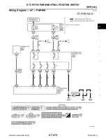
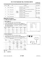
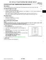
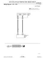
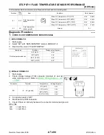
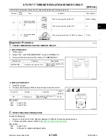
TCM terminals and data are reference value. Measured between each terminal and ground.
Diagnostic Procedure
ECS009E3
1.
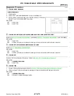
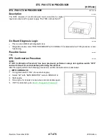
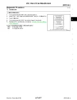
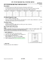
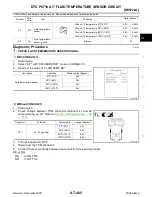
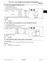
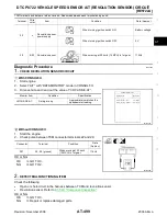
CHECK FLUID TEMPERATURE SENSOR SIGNAL
With CONSULT-II
1.
Start engine.
2.
Select “A/T” with “DATA MONITOR” mode in CONSULT-II.
3.
Read out the value of “FLUID TEMP SE”.
Without CONSULT-II
1.
Start engine.
2.
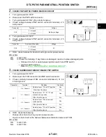
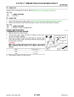
Check voltage between TCM connector terminals 41 and 42
while warming up A/T. Refer to
.
3.
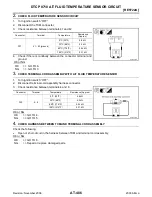
Turn ignition switch “OFF”.
4.
Disconnect the TCM connector.
5.
Check if there is continuity between the connector terminal and ground.
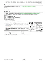
OK or NG
OK >> GO
TO
6.
NG
>> GO TO 2.
Terminal
Wire
color
Item
Condition
Data (Approx.)
41
R/Y
Fluid temperature
sensor
When ATF temperature 0
°
C (32
°
F)
4.0V
9.8 k
Ω
When ATF temperature 20
°
C (68
°
F)
3.0V
4.2 k
Ω
When ATF temperature 80
°
C (176
°
F)
0.8V
.54 k
Ω
When ATF temperature 100
°
C (212
°
F)
0.5V
.31 k
Ω
42
LG
Fluid temperature
sensor ground
Always
0V
Item name
Condition
Display value (Approx.)
Fluid temperature sensor
0
°
C (32
°
F)
4.0V
20
°
C (68
°
F) 3.0V
80
°
C (176
°
F)
0.8V
100
°
C (212
°
F)
0.5V
SCIA2870E
Connector
Terminal
Temperature
Voltage (Approx.)
F57
41 - 42 (ground)
0
°
C (32
°
F)
4.0V
20
°
C (68
°
F)
3.0V
80
°
C (176
°
F)
0.8V
100
°
C (212
°
F)
0.5V
SCIA2871E

