

AT-4
Revision: November 2006
2006 Altima
Reduction Pinion Gear ......................................... 383
Band Servo ........................................................... 384
Output Shaft ......................................................... 384
Bearing Retainer ................................................... 385
Total End Play ....................................................... 385
Reverse Clutch End Play ...................................... 385
Removal and Installation ...................................... 385
Shift Solenoid Valves ............................................ 385
Solenoid Valves .................................................... 385
A/T Fluid Temperature Sensor .............................. 386
Revolution Sensor ................................................ 386
Dropping Resistor ................................................. 386
Turbine Revolution Sensor (Power Train Revolution
Sensor) ................................................................. 386
RE5F22A
INDEX FOR DTC ..................................................... 387
Alphabetical Index ................................................ 387
DTC No. Index ...................................................... 388
PRECAUTIONS ....................................................... 389
Precautions for Supplemental Restraint System
(SRS) “AIR BAG” and “SEAT BELT PRE-TEN-
SIONER” ............................................................... 389
Precautions for On Board Diagnostic (OBD) System
of A/T and Engine ................................................. 389
Precautions for A/T Assembly or TCM Replacement .390
Precautions ........................................................... 391
Service Notice or Precautions .............................. 393
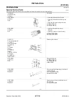
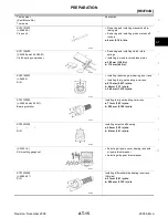
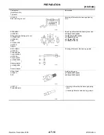
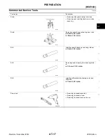
PREPARATION ....................................................... 394
Special Service Tools ........................................... 394
Commercial Service Tools .................................... 397
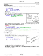
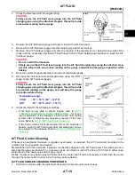
A/T FLUID ............................................................... 398
Changing A/T Fluid ............................................... 398
Checking A/T Fluid ............................................... 398
A/T Fluid Cooler Cleaning .................................... 399
A/T CONTROL SYSTEM ........................................ 403
Cross-Sectional View ............................................ 403
Shift Mechanism ................................................... 404
TCM Function ....................................................... 421
Input/Output Signal of TCM .................................. 422
CAN Communication ............................................ 422
Line Pressure Control ........................................... 423
Shift Control .......................................................... 423
Lock-Up Control .................................................... 425
ON BOARD DIAGNOSTIC (OBD) SYSTEM .......... 427
Introduction ........................................................... 427
OBD-II Function for A/T System ........................... 427
One or Two Trip Detection Logic of OBD-II .......... 427
OBD-II Diagnostic Trouble Code (DTC) ............... 427
Malfunction Indicator Lamp (MIL) ......................... 430
TROUBLE DIAGNOSIS .......................................... 431
DTC Inspection Priority Chart ............................... 431
Fail-Safe ............................................................... 431
How To Perform Trouble Diagnosis For Quick and
Accurate Repair .................................................... 434
A/T Electrical Parts Location ................................. 439
Circuit Diagram ..................................................... 440
Inspections Before Trouble Diagnosis .................. 441
Check Before Engine is Started ............................445
Check at Idle .........................................................445
Cruise Test - Part 1 ...............................................447
Cruise Test - Part 2 ...............................................448
Cruise Test - Part 3 ...............................................449
Shift Schedule .......................................................450
Symptom Chart .....................................................451
TCM Input/Output Signal Reference Values .........459
CONSULT-II Function (TCM) ................................462
Diagnostic Procedure Without CONSULT-II .........468
DTC U1000 CAN COMMUNICATION LINE ............471
Description ............................................................471
On Board Diagnosis Logic ....................................471
Possible Cause .....................................................471
DTC Confirmation Procedure ................................471
Wiring Diagram — AT — CAN ..............................472
Diagnostic Procedure ............................................473
DTC P0500 VEHICLE SPEED SENSOR MTR .......474
Description ............................................................474
On Board Diagnosis Logic ....................................474
Possible Cause .....................................................474
DTC Confirmation Procedure ................................474
Diagnostic Procedure ............................................475
DTC P0613 TCM PROCESSOR .............................476
Description ............................................................476
On Board Diagnosis Logic ....................................476
Possible Cause .....................................................476
DTC Confirmation Procedure ................................476
Diagnostic Procedure ............................................477
DTC P0705 PARK/NEUTRAL POSITION SWITCH .478
Description ............................................................478
On Board Diagnosis Logic ....................................478
Possible Cause .....................................................478
DTC Confirmation Procedure ................................478
Wiring Diagram — AT — PNP/SW .......................479
Diagnostic Procedure ............................................480
Component Inspection ..........................................482
Description ............................................................483
On Board Diagnosis Logic ....................................483
Possible Cause .....................................................483
DTC Confirmation Procedure ................................483
Wiring Diagram — AT — FTS ...............................484
Diagnostic Procedure ............................................485
Component Inspection ..........................................487
Description ............................................................488
On Board Diagnosis Logic ....................................488
Possible Cause .....................................................488
DTC Confirmation Procedure ................................488
Wiring Diagram — AT — FTSP ............................489
Diagnostic Procedure ............................................490
Component Inspection ..........................................492