


AT32F425
Series Reference Manual
2022.03.30
Page 301
Ver 2.01
If the preempted channel trigger occurs during the ordinary channel conversion, then the ordinary
channel conversion is interrupted, giving the priority to the preempted channel, and the ordinary channel
continues its conversion at the end of the preempted channel conversion. If the ordinary channel trigger
occurs during the preempted channel conversion, the ordinary channel conversion won’t start until the
end of the preempted channel conversion.
Program the ADC_Inx into the ordinary channel sequence (ADC_OSQx) and the preempted channel
sequence (ADC_PSQ), and the same channel can be repeated, the total number of sequences is
determined by OCLEN and PCLEN, then it is ready to enable the ordinary channel or preempted channel
conversion.
18.4.1.1 Internal reference voltage
The internal reference voltage of the typical value 1.2 V is connected to ADC1_IN17. It is required to
enable the ITSRVEN bit in the ADC_CTRL2 register before the internal reference channel conversion.
The converted data of such channel can be used to calculate the external reference voltage.
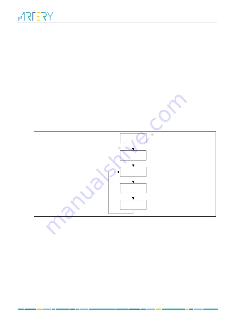
18.4.2 ADC operation process
shows the basic operation process of the ADC. It is recommended to do the calibration
after the initial power-on in order to improve the accuracy of sampling and conversion. After the
calibration, trigger is used to enable ADC sampling and conversion. Read data at the end of the
conversion.
Figure 18-2
ADC basic operation process
Power-on
Calibration
Trigger
ADC
conversion
Read data
18.4.2.1 Power-on and calibration
Power-on
Set the ADCxEN bit in the CRM_APB2EN register to enable ADC clocks: PCLK2 and ADCCLK.
Program the desired ADCCLK frequency by setting the ADCDIV bit in the CRM_CFG register. The
ADCCLK is derived from PCLK2 frequency division.
Note: ADCCLK must be less than 28 MHz.
Then set the ADCEN bit in the ADC_CTRL2 register to supply the ADC, and wait until the RDF flab is
set before starting ADC conversion. Clear the ADCEN bit will stop the ADC conversion and result in a
reset. In the meantime, the ADC is switched off to save power.
Calibration
After power-on, the calibration is enabled by setting the ADCAL bit in the ADC_CTRL2 register. When
the calibration is complete, the ADCAL bit is cleared by hardware and the conversion is performed by
software trigger.
After each calibration, the calibration value is stored in ADC_ODT register, and then value is
automatically sent back to the ADC so as to eliminate capacitance errors. The storage of the calibration


