AT32F425
Series Reference Manual
2022.03.30
Page 188
Ver 2.01
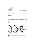
Figure 14-3
Overflow event when PRBEN=0
0
1
2
3
...
31
32
0
1
2
3
...
31
32
0
1
2
3
COUNTER
31
32
0
1
32
...
PR[15:0]
OVFIF
TMR_CLK
0
DIV[15:0]
22
Clear
Clear
Clear
Figure 14-4
Overflow event when PRBEN=1
0
1
2
3
...
21
22
0
1
2
3
...
31
32
0
1
2
3
COUNTER
31
32
0
1
32
...
PR[15:0]
OVFIF
TMR_CLK
0
DIV[15:0]
22
Clear
Clear
Clear
Figure 14-5
Counting timing diagram when the prescaler division is 4
TMR_CLK
CNT_CLK
COUNTER
OVFIF
32
31
30
2F
4
DIV[15
:
0]
0
1
2
32
PR[15
:
0]
Clear
14.1.3.3 Debug mode
When the microcontroller enters debug mode (Cortex
®
-M4 core halted), the TMRx counter stops
counting when the TMRx_PAUSE bit is set.
14.1.4 TMR6 and TMR7 registers
These peripheral registers must be accessed by word (32 bits).
In Table 14-2, all the TMRx registers are mapped to a 16-bit addressable space.
Table 14-2 TMR6 and TMR7
— register table and reset value
Register
Offset
Reset value
TMRx_CTRL1
0x00
0x0000
TMRx_CTRL2
0x04
0x0000
TMRx_IDEN
0x0C
0x0000
TMRx_ISTS
0x10
0x0000
TMRx_SWEVT
0x14
0x0000
TMRx_CVAL
0x24
0x0000
TMRx_DIV
0x28
0x0000
TMRx_PR
0x2C
0x0000
14.1.4.1 TMR6 and TMR7 control register1 (TMRx_CTRL1)
Bit
Register
Reset value
Type
Description
Bit 15: 8
Reserved
0x00
resd
Kept at its default value.
Bit 7
PRBEN
0x0
rw
Period buffer enable