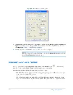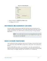
4-4
Single Scan Operation
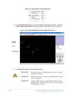
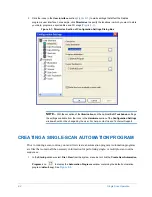
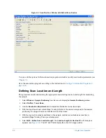
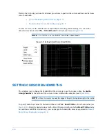
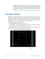
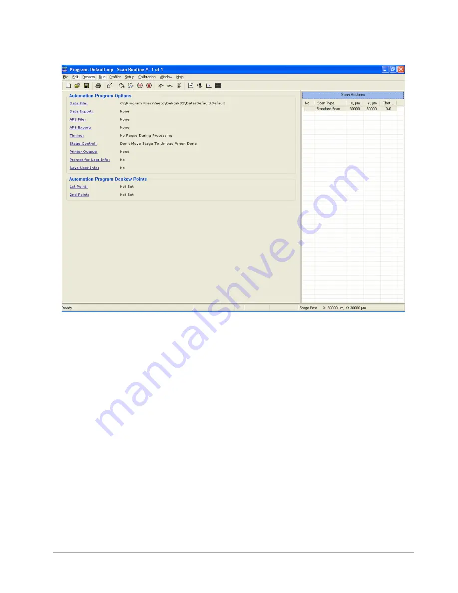
Figure 4-3: Scan Routines Window with Default Scan Routine
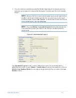
You can edit the options for this automation program and add or modify scan routine parameters (see
Save the automation program according to the instructions in
Saving an Automation Program on
.
Defining Scan Location and Length
This procedure entails determining the appropriate scan starting location and length for measuring
the sample.
1
Select
Window
>
Sample Positioning
from the menu to display the
Sample Positioning
window.
2
Select
Profiler
>
Tower Down
.
3
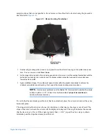
Use the
Illumination Adjustment
icons to adjust the illumination to view the sample.
4
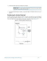
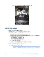
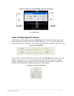
With the stylus tower down, initiate Stage Tracking (left-click in the camera view pane) for fine sample
positioning. The image should now track the motion of the mouse.
5
With the stylus reticle properly positioned on the sample, click the mouse button a second time to
deactivate Stage Tracking. This is your starting point.
6
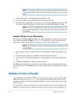
Select
Edit
>
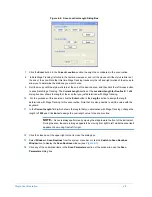
Define Scan Location/Length
. The
Location/Length for Routine #: 1 of 1
dialog box
appears (see
X
,
Y
, and
T
fields display the current X-Y stage position.
Содержание Dektak 150
Страница 1: ......
Страница 2: ...P N 980 294 Standard P N 980 298 Cleanroom Revision A DEKTAK 150 SURFACE PROFILER USER S MANUAL ...
Страница 7: ......
Страница 17: ......
Страница 81: ......
Страница 105: ......
Страница 149: ......
Страница 191: ......
Страница 251: ......
Страница 257: ...A 6 Facilities Specifications Figure A 6 Dektak 150 without Enclosure Side View ...
Страница 258: ...Facilities Specifications A 7 Figure A 7 Dektak 150 Dimensions without Enclosure Top View ...
Страница 259: ...A 8 Facilities Specifications Figure A 8 Dektak 150 without Enclosure Center of Mass ...
Страница 273: ......
Страница 283: ......
Страница 320: ...3D Mapping Function E 37 Figure E 26 Database Options Button Figure E 27 Database Options Dialog Box ...
Страница 321: ......
Страница 331: ......
Страница 333: ......
Страница 336: ......
Страница 337: ......
Страница 349: ......

