


Creating a Point
SECTION 3 Points
42
The Array Size: field specifies the number of data values associated with the
point. A value greater than 1 allows the point to be treated as an array. For
more detail on array points and their uses see Optimisation of PLC
Communications.
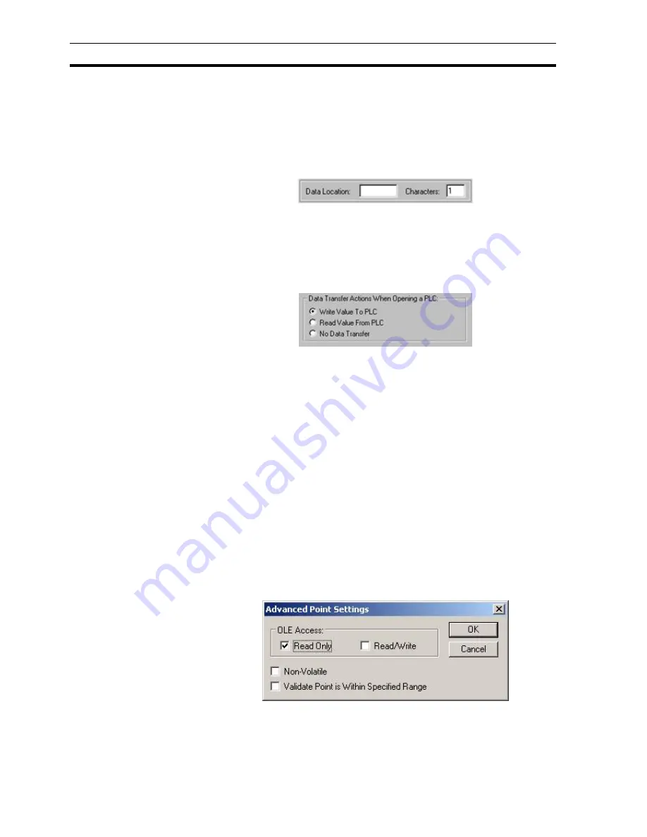
The PLC Attributes dialog box takes on a slightly different appearance if the
point type is text, showing the number of characters which start at the
specified data location:
3-4-9
Data Transfer Actions When Opening a PLC
The type of data transfer action for the selected PLC can be specified by
selection of the appropriate setting. Options for Input and Input/Output points
are Always Update Point Value and Only Update Point Value When On
Display. Options for an Output point are Write Value, Read Value and No Data
Transfer.
3-4-10 Conversion Attributes
The minimum and maximum PLC value and the application of a conversion
factor is specified in the Conversion Attributes: fields (these fields are not
applicable for Boolean and text points).
Conversion Attributes can be used to convert in a linear fashion between a
value in a PLC and the point range. For example, if the possible range in the
PLC is 0 to 1000, and the point range is 0 to 100, then a PLC value of 500
would correspond to a point value of 50. The conversion would be performed
just before the data is sent to the PLC, or immediately upon receipt of it from
the PLC.
On completion of the PLC configuration connection, click the OK button to
continue, or the Cancel button to abort. Click the Add PLC button to create a
new PLC connection. Information relating to the selection of this button is
described in chapter 6 Projects, Device Configuration.
3-4-11 Advanced Point Settings
Advanced settings can be applied to a new point, by clicking the
Advanced
button in the
Add Point
dialog box. This results in the
Advanced Point
Settings
dialog box being displayed.
In order to access a CX-Supervisor point value via OLE2 Automation, it must
be given OLE Read or OLE Write access. The scope of the access can be
defined by checking the appropriate setting in the OLE Access.
Содержание CX-Supervisor
Страница 1: ...CX Supervisor Software Cat No W10E EN 01 User Manual Software Release 3 1...
Страница 3: ...Copyright Notice 2...
Страница 16: ...15...
Страница 17: ...16...
Страница 27: ...Tip of the Day SECTION 1 Graphics Editor 26...
Страница 35: ...CX Supervisor Preferences SECTION 2 Pages 34...
Страница 79: ...Responding to Events SECTION 5 ActiveX Objects 78...
Страница 115: ...Printing the Graphics Library SECTION 7 Graphics Library 114...
Страница 181: ...Data Logging SECTION 11 Data Logging 180...
Страница 201: ...Examples SECTION 12 Databases 200...
Страница 243: ...Performance Monitor SECTION 16 Application Analysis Performance Monitor 242...
Страница 253: ...Using with Omron s CX Server OPC SECTION 17 Using CX Supervisor as an OPC Cli 252...
Страница 259: ...Creating a CX Supervisor Client application SECTION 18 Connecting to a remote CX 258...
Страница 263: ...Adding a Point Linked to a Parameter SECTION 19 Connecting to Omron Industrial 262...
Страница 271: ...Data Logging SECTION 20 Best Practices 270...
Страница 275: ...Configuring a Server PC running Windows NT or 2000 Appendix A Configuring a PC 274...
Страница 277: ...Appendix B Frequently Asked Questions 276...
Страница 296: ...Appendix B Frequently Asked Questions 295...
Страница 297: ...Appendix B Frequently Asked Questions 296...
Страница 298: ...Appendix B Frequently Asked Questions 297...
Страница 299: ...Appendix B Frequently Asked Questions 298...
Страница 333: ...Revision history 332...


