Thrusters
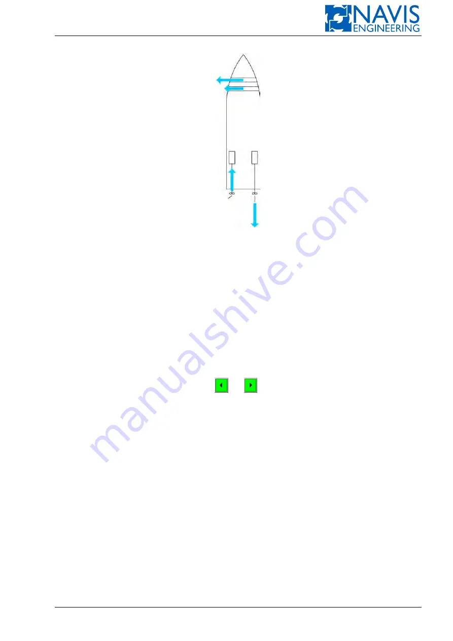
Figure 6.23: Thrust Allocation
The demand for
F
and
M
must then be shared by the thrusters from the Auto Thruster Group, which is performed by
the Thruster Allocation Function. This function assigns the thrust demand to each thruster from the Auto Thruster Group.
The figure 6.23 demonstrates that there are many ways in which a combination of
F
and
M
can be shared by the
thrusters. The Thruster Allocation Function always does it in an optimal manner, with many limitations taken into ac-
count.
6.2.3
Thruster Control
In normal operation, a thruster can be controlled whether manually or automatically. We say the thrusters controlled
manually (respectively, automatically) to constitute the
Manual
(respectively,
Auto
)
Thruster Group
.
When the thruster is included into the Manual Thruster Group, its thrust demand is set independently from other
thrusters and no command comes to it except the command that can be input manually from Manual Thruster window.
The thruster does not participate in joystick/knob control as well as automatic control.
In this case, the thruster softkey is dark green.
and
softkeys can be used in Manual Thruster window to
control the thruster. These softkeys are light green. When pressing these softkeys, the thrust demand (the green line) can
be changed.
The thruster control system controls the thruster so as to provide the actual thrust equal to the demand (the yellow
line). For an azimuth thruster, you can set the thrust direction (azimuth) to be controlled manually, while the thrust itself
is included in the Auto Thruster Group.
If you are going to include an automatically controlled thruster (with softkey green) in the Manual Thruster Group
press the thruster softkey and then press ENTER to acknowledge. To remove a thruster from the Manual Thruster Group
(and thus include in Auto Thruster Group), do the same.
6.2.4
Interface with the Thrusters
6.2.4.1
Interface Signals
NAVIS NavDP 4000
interfaces to each thruster by means of the signals listed below.
Run
(Available for DP) Signal from thruster to
NAVIS NavDP 4000
and means that
– the thruster motor is running without any fault;
– thruster control can be transferred to the
NAVIS NavDP 4000
at any time upon the
NAVIS NavDP 4000
request.
Select
Signal from
NAVIS NavDP 4000
to a thruster and means that the
NAVIS NavDP 4000
is going to take control
over the thruster.
Doc. 000.JDP-10000-OME, rev.3.3.13/“2102.$–17A-Advanced”
112
Содержание NavDP 4000 Series
Страница 88: ...NAVIS NavDP 4000 Operation Manual Figure 5 35 Dark Theme 87 Doc 000 JDP 10000 OME rev 3 3 13 2102 17A Advanced...
Страница 222: ...NAVIS NavDP 4000 Operation Manual Figure 10 74 Drift Plot Window 221 Doc 000 JDP 10000 OME rev 3 3 13 2102 17A Advanced...
Страница 324: ...NAVIS NavDP 4000 Operation Manual Figure H 4 Remote DLS Mode 323 Doc 000 JDP 10000 OME rev 3 3 13 2102 17A Advanced...


