background image

76

Removing The  Bag

IMPORTANT: Monitor the length of the bag 
and the number of folds remaining on the 
tunnel.  Start the following procedure when 
there is 6 to 7 folds remaining on the tunnel.

1. 

Prior to the last load pull the anchors in 
using the anchor switch on the right side 
console.  Increase the brake pressure on 
the engine and cab end brakes pressing 
the top (+) of the pressure switches on 
the right front corner cab post.  Watch the 
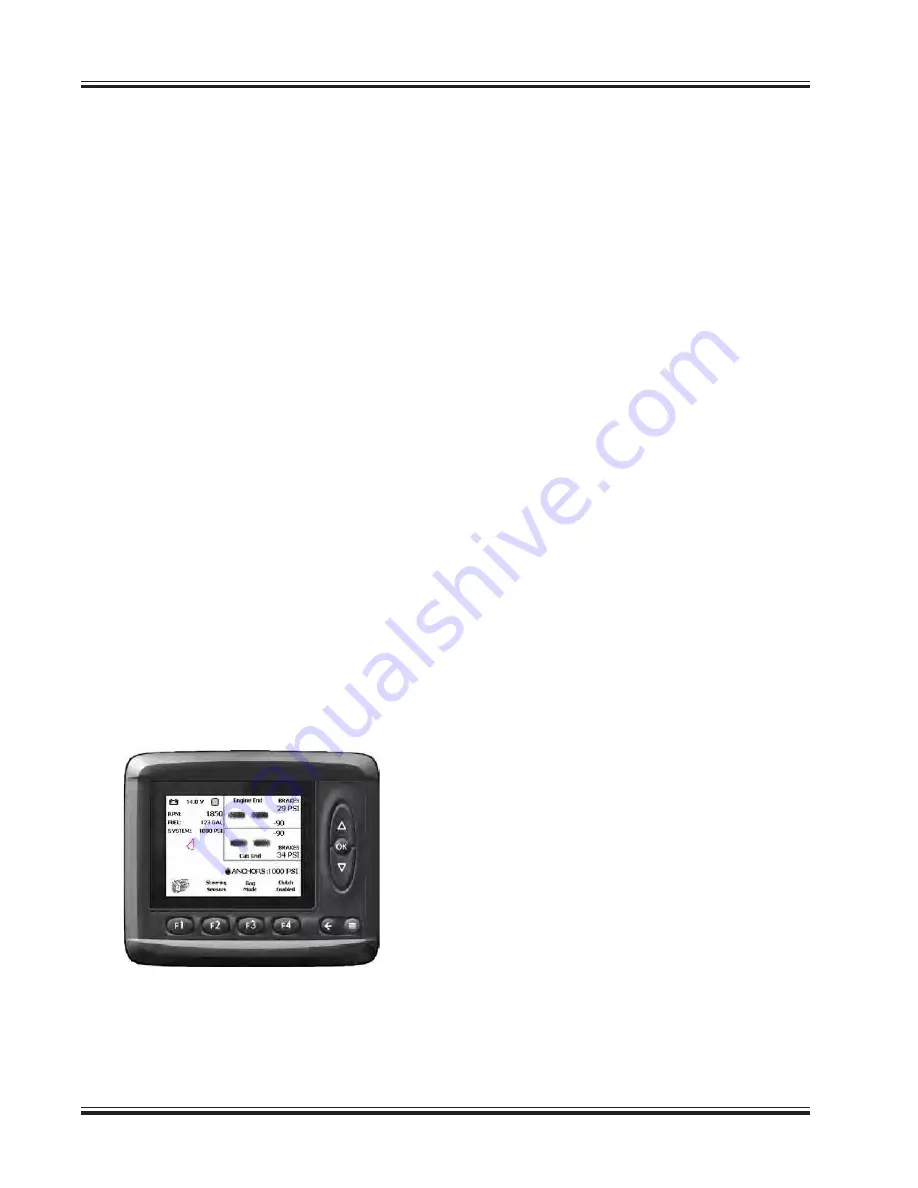
System Monitor display for brake pressure 
at each end.  When the final load is in the 
bag there should be approximately 5 folds 
left on the tunnel.

IMPORTANT: If using the inoculant applica-
tor, turn it off at this time.

2. 

Release the brake pressure on the cab 
and engine end brakes by pressing the 
bottom (-) of the brake pressure switches 
on the front right corner cab post.  Watch 
the System Monitor display for brake pres-
sure at each end.

IMPORTANT: Always turn the rotor off before 
activating the tunnel cleanout.  Do not turn 
the rotor on unless the tunnel clean out is 
completely closed.

3. 

Drive the bagger away from the end of the 
bag approximately four feet to allow the 
tunnel cleanout to operate properly.

4. 

Push and hold the top of the cleanout 
switch on the right side console to open 
(push away from rotor) the tunnel clean 
out.  When the tunnel clean out is open an 
icon will appear on the display panel on the 
right side corner post alerting the operator 
that the clean out is open.

5. 

Push and hold the bottom of the cleanout 
switch to close (bring it toward the rotor) 
the tunnel clean out.  Once the tunnel 
clean out is completely closed, the icon on 
the display will disappear.  Do not turn the 
rotor on unless the icon has disappeared.

6. 

Open and close the tunnel cleanout sev-
eral times to move as much product as 
possible into the bag.

7. 

Pull the bagger forward until the bag has 
been pulled from the tunnel.

8. 

After the bagger has been moved away, 

pull the plastic flat and prepare to seal the 
end of the bag.  Grab each side of the bag 
on the end.  Walk the bag over itself pulling 
the product together.  Bring the bag end 
back forward.

9. 

Seal the end of the bag using either Mas-
ter Seal strips or the double tie method.  
Refer to “Bagging Instructions” for addi-
tional information.

NOTE:

 No matter which method is used when 

sealing the end of the bag, loose plastic should 
be weighted down.  Do Not use material that will 
be abrasive to the bag material.

Install the vent into the bag.  See Venting the 
Bag.

Tunnel Cleanout Open Icon

Содержание AG-BAG Professional LX1214

Страница 1: ...P O BOX 127 ST NAZIANZ WI 54232 920 773 2121 FAX 920 773 1200 OPERATOR S MANUAL DO NOT OPERATE THIS EQUIPMENT UNTIL THIS MANUAL HAS BEEN READ AND UNDERSTOOD Part Number 42 0802219B December 2014 MODE...

Страница 2: ...operation Failure to follow the recommended procedures may result in personal injury or equipment damage and could void the warranty MACHINE SERIAL NUMBER The machine serial number is located on the...

Страница 3: ...nchor Switch In Out 23 Engine Throttle Control Switch 24 Engine High Idle Switch 24 Tunnel Clean Out Switch 25 Feed Table Lift Lower Switch 25 Engine End Lift Jack Switch 26 Cab End Lift Jack Switch 2...

Страница 4: ...er From Fuel Filter Water Separator 52 Engine Coolant Conditioner Filter Extended Life Coolant Only 52 Engine Coolant Filter Organic Acid Technology OAT Coolant Only 52 CHANGING TUNNELS 53 OPERATION 6...

Страница 5: ...lt Codes QSX Engines 94 Trouble Shooting 102 FUSE RELAY LOCATIONS 104 LUBRICATION 105 Rotor Bearing 105 Feed Table Drive and Idler Rollers 105 Lower Beater Bar Bearings 106 Upper Beater Bar Bearings 1...

Страница 6: ...ogy OAT Coolant 130 Changing Coolant Types 130 Definitions Of Coolant Types 130 Engine Air Cleaner Filters 131 Engine Serpentine Belts 132 Air Storage Tank 133 Bag Boom Winch Oil 134 HYDRAULIC SYSTEMS...

Страница 7: ...escription Part Number Qty Primary Air Filter Element 42 0800816 1 Secondary Air Filter Element 42 0800817 1 Fuel Filter Water Separator 42 0801373 1 Engine Oil Filter 42 0801370 1 Engine Coolant Cond...

Страница 8: ...ry and Pre Delivery Check Lists customer and dealer copies follow this page Customer copies can remain with this manual Dealer copies can be removed along perforation and remain with dealer Bagger Che...

Страница 9: ...perate the unit Review the warranty Explain and review the safety section of this manual with the customer Explain that regular lubrication and proper adjustments are required for continued proper op...

Страница 10: ...d Verify that all accessories function correctly Check tire inflation Check and tighten wheel nuts to correct torque Make sure all bolts and other fasteners are tightened or properly adjusted Make sur...

Страница 11: ...rate the unit Review the warranty Explain and review the safety section of this manual with the customer Explain that regular lubrication and proper adjustments are required for continued proper op er...

Страница 12: ...Verify that all accessories function correctly Check tire inflation Check and tighten wheel nuts to correct torque Make sure all bolts and other fasteners are tightened or properly adjusted Make sure...

Страница 13: ...y result in minor or moderate injury It may also alert against unsafe practices BEFORE you attempt to operate this machine read and study the following safety informa tion In addition MAKE SURE that e...

Страница 14: ...is operating Keep hands feet and clothing away from feed table when operating Do not allow people other than a qualified operator near the unit Keep riders off the bagger Do not allow passengers Do n...

Страница 15: ...der pressure can penetrate skin causing seri ous injury or death Avoid the edges of ditches or gullies and steep hillsides Only operate bagger on level ground Reduce speed on rough ground Be extra car...

Страница 16: ...hine Be sure to use the proper tools Be sure to torque all hardware according to the torque chart contained in this manual Use a piece of cardboard or paper to check for hydraulic oil leaks Do not use...

Страница 17: ...with your hand High pressure oil or fuel can cause personal injury To prevent suffocation and frostbite wear protective clothing and ONLY disconnect liquid refrigerant freon lines in a well ventilate...

Страница 18: ...Inspect all components for damage after any electrical problem There are additional hazards associated with the service and maintenance of electrical components All electrical components generate heat...

Страница 19: ...that the rim could fail resulting in personal injury or severe damage to the bagger Replace any leaking or damaged wheels with New wheels Do not rework weld heat or braze rims If you have a wheel on y...

Страница 20: ...14 Safety Sign and Decal Locations...

Страница 21: ...15 Safety Sign and Decal Locations continued...

Страница 22: ...20178 Ref 7 Warning Before Operating Qty 1 16 20181 Ref 6 Warning Rotating Parts Inside Qty 2 16 20179 Ref 5 Warning Shield Is Off Or Open Qty 1 Disconnect both positive and negative battery cables a...

Страница 23: ...CONNECT POWER BEFORE SERVICING FAILURE TO HEED WILL RESULT IN DEATH OR PERSONAL INJURY 42 0900821 42 0900821 Ref 10 Moving Conveyor Danger Qty 4 42 0900820 Ref 11 Revolving Rotor Danger Qty 6 21 09025...

Страница 24: ...ls SMV Emblem Red Reflective Decal Yellow Reflective Decal Cab Platform Yellow Reflective Decal Wheel Pivot Cab End Yellow Reflective Decal Wheel Pivot Engine End Feed Table Side Red Reflective Decal...

Страница 25: ...ic Clutch Oil Reservoir Capacity 20 Gal 76 L Hydraulic Clutch Oil Type Mobil 424 ROTOR PLANETARY GB13000 Planetary System Oil Capacity 7 5 Gal 28 L Planetary Oil Type Synthetic 80W 140 Gear Lube FEED...

Страница 26: ...ckwise B Signal Light Switch Red Green On Off C Signal Light Switch Amber On Off D Inoculant Spray Applicator Switch On Off E Anchor Float Switch On Off F Anchor Switch In Out G Engine Throttle Contro...

Страница 27: ...ater Control Switch Signal Light Switch Red Green Location B The signal light switch for the red green signal lights is a three position rocker switch which turns the red or green signal lights on and...

Страница 28: ...ge for each light Inoculant Spray Applicator Switch Inoculant Spray Switch Inoculant Spray Applicator Switch Location D The inoculant spray applicator switch is a two position rocker switch which turn...

Страница 29: ...he anchors to float out when starting a new bag Anchor Float Switch Anchor Float Switch Anchor Switch In Out Location F The anchor in out switch is a three position mo mentary switch which powers the...

Страница 30: ...ing at when the switch was released Engine Throttle Switch Engine Throttle Switch Engine High Idle Switch Location H The engine high idle switch is a two position on off switch Push the top of the swi...

Страница 31: ...tor on unless the icon has disappeared Tunnel Clean Out Switch Tunnel Clean Out Switch Feed Table Lift Lower Switch Location J The feed table lift lower switch is a three position momentary switch whi...

Страница 32: ...ed to rotate the wheels into position Cab End Lift Jack Switch Location L The cab end lift jack switch is a three position momentary switch which must be held in posi tion When the switch is released...

Страница 33: ...Port w Cap Removed Brake Pedal The brake pedal is located on the cab floor between the operators seat and the windshield The brake pedal is used to apply the wheel brakes when moving the vehicle and...

Страница 34: ...in the direction you want to travel Drive is forward or backward 4 Wheels at the cab end and engine end are steered independently using the joystick Cab end wheels are steered by moving the joystick...

Страница 35: ...nd only The elec tronic control system will steer the cab end wheels Wheels will Crab steer wheels stay parallel Move the joystick front to back to steer Switching Driving Modes The modes can be switc...

Страница 36: ...ode will display Switch From Trailer to Transport Mode Trailer to transport A Wheels at engine and cab ends must be within 5 degrees of each other B When this is true press the F3 key on the display C...

Страница 37: ...Drive Press This End For Align Display for Bag Mode Display for In Between Mode 6 Steer the engine end wheels to 90 degrees 2 degrees 7 Lower the engine end wheels to the ground by lifting the jack a...

Страница 38: ...the belt The joystick is friction controlled and will maintain any setting Always stop the feed table belt between loads and while leaving the bagger unattended Feed Table Belt Control Joystick Two Wa...

Страница 39: ...s digits flash 4 Rotate the SETUP knob to change the hour Rotating the knob clockwise will in crease the hour rotating counterclockwise will decrease the hour 5 Press the DISPL TIME button again caus...

Страница 40: ...tely press the BAND button once When the radio displays USA do not press any buttons until the radio display returns to the current time Setting the radio for frequencies outside of North America 1 Tu...

Страница 41: ...ition Switch Parking Brake The parking brake control is a pull to apply push to release control It is located on the right side corner post of the cab above the system pres sure gauge and the ignition...

Страница 42: ...ed on the right side corner post The switches are used to increase or decrease the brake pressure during bagging Press the top of the required switch to increase the pres sure When released the switch...

Страница 43: ...make sharp turns Push the bottom of the switch in for four wheel drive In this position all four wheels will be driving Use this position for bagging mode and trailer mode for driving on to and off of...

Страница 44: ...e functions indicated and LED indicators on the face of the controller The following is a list of what each LED on the controller represents Refer to the controller panel face at the bottom of this pa...

Страница 45: ...off position The ignition switch must be in the run position for the windshield wiper to work To activate the windshield washer press and hold the top of the wiper switch in The washer will be activat...

Страница 46: ...erature to stabilize If cab is still too cool turn the temperature con trol knob toward Max Hot until the air tempera ture is comfortable If the compressor stays off for 3 to 4 minutes and the air sta...

Страница 47: ...the switch in to turn the lights off This switch controls the outer and inner lights at the top front of the cab Bagger Light Switches Field Switch Switch C Push the top of the switch in to turn the...

Страница 48: ...Switches B and C Road Lights Field Lights Feed Table Lights Switch D Boom Light Switch D Under Cab and Air Cleaner Lights Switch A Light Under Platform Light Under Air Cleaner Lights Front and Rear Co...

Страница 49: ...circulation filter and storage tray before operating Storage Tray removed from behind training seat Recirculation Filter removed from below storage tray Cab Pressurization Filter Char coal On the outs...

Страница 50: ...Handles The outside door handle is equipped with a key lock This lock uses the same key as the igni tion Push the button to open the door from the outside The inside door release is a squeeze release...

Страница 51: ...or is located on the side of the right side cab corner post Engine Data Link Connector Inside Cab Engine Data Link System Monitor Programming Port The System Monitor programming port is lo cated below...

Страница 52: ...nto position IMPORTANT The bag boom is designed to be used for positioning the tunnel extension and to install bags onto the tunnel Bag Pan In or Out This control will position the bag pan in or out a...

Страница 53: ...mote Control Connection Point Use the switches on the remote to operate the bag boom and bag pan All the switches on the remote are spring loaded and will return to the center Off position when releas...

Страница 54: ...p or Down This control is used to lift or lower the cab end of the bagger by lower ing or raising the lift jack at the cab end It is located on the frame next to the inoculant tank DANGER To prevent p...

Страница 55: ...ower drain on the batteries then turn the switch to the OFF position when the bagger is not being used this will disconnect the batteries from the bagger electrical system Remote Battery Terminals The...

Страница 56: ...ur dealer for or dering Available plug 21 22619 can be ordered from your dealer The power strip is located to the right of the operators seat next to the side window Auxiliary Power Outlet The auxilia...

Страница 57: ...d too full then left in direct sunlight or if tempera ture rises after refueling the tank will overflow The fuel tank is located under the lift up cover walkway between the feed table beater plate and...

Страница 58: ...Fuel Filter Water Separator Drain Engine Coolant Conditioner Filter Extended Life Coolant Only Locate the coolant conditioner filter on the side of the engine Be sure the indicator arrow on the valve...

Страница 59: ...linders To change the tunnel proceed as follows 1 Start the engine and lower the bag pan all the way down Shut off the engine and remove the key Bag Pan Lowered Crane Attached To Tunnel Loop Two Piece...

Страница 60: ...to the frame Save the button head bolts and nuts for reassembly 6 Pull the two anchor cables through the pullies under the tunnel floor Remove the cable retainer pin next to the pulley Save the pin f...

Страница 61: ...or that hold the tunnel to the frame Remove all three bolts Save all hardware for reassembly Note early production had flat head bolts current pro duction has hex head bolts 8 Remove the seven 3 4 bol...

Страница 62: ...Lower four bolts shown Chain Guard 10 Remove the guard over the chains at the driven end of the rotor on the feed table side This is to access the three allen flat head bolts inline with the rotor th...

Страница 63: ...hat the tunnel is stable 14 Locate the plate on the cab side of the upper tunnel that holds the tunnel to the frame Loosen the five bolts from one end of the plate and remove the four bolts from the o...

Страница 64: ...nt to the tunnel with 5 8 11 x 2 bolts and 5 8 SAE flat washers 5 Secure the left side tunnel mount to the engine end of the tunnel in the same man ner 6 Lift the tunnel up with the overhead hoist and...

Страница 65: ...e frame On the cab end of the tunnel also assemble the anchor indicator cable roller to the lower bolt of the tunnel mount Tighten securely 12 Assemble the tunnel floor to the frame us ing the 5 8 11...

Страница 66: ...end of the bag ger This hand rail is used to fill the gap between the platform hand rail and the tunnel Position the handrail next to the platform hand rail from the tunnel side Se cure the hand rail...

Страница 67: ...eath will result 1 If the engine has been idle for a long pe riod of time it may be necessary to bleed the fuel lines and use the hand primer pump on the fuel filter to charge the lines with fuel See...

Страница 68: ...The engine is equipped with a block heater to aid in cold weather starting The block heater cord is located next to the engine oil filter Inoculant Applicator Operation The amount of inoculant applied...

Страница 69: ...RC11003 XRC11004 XR11001 XR110015 XRC11002 XRC11002 XRC110025 XRC110025 XRC11003 AG BAG PART NO 07 08287 07 08288 07 08289 07 08290 07 08290 07 17242 07 17242 07 17269 07 17735 07 09647 07 09647 07 08...

Страница 70: ...end wheel Use the existing pins to secure in place Position Bagger At Bagging Site Drive the bagger to the spot where the bag is to begin Position the bagger with the tunnel to ward the bag starting p...

Страница 71: ...gn switch on the switch pan el on the right side corner post steer the wheels to within 5 degrees then press the Drive switch Cab end wheels will steer automatically to match the engine end Display fo...

Страница 72: ...el ex tension out and lower to a position in front of the tunnel Line up the five pins on the extension with the five receiver tubes on the tunnel Slide the tunnel extension pins into the receiver tub...

Страница 73: ...switch when the feed table reaches the ground 3 Lift the side panels up until the spring loaded locks enter into the lock plate hole The locks can be pulled up and rotated to remain in the unlocked up...

Страница 74: ...s section of this manual Bag Identification Arrow Bag Size Remove Anchors From Storage Hooks Before placing the bag onto the tunnel the two anchors have to be removed from the storage hooks 1 Remove t...

Страница 75: ...x and remove the outer lid DO NOT remove the ties around the bag until the bag is on the tunnel Remove the inner shell and the box will flatten Bag Cradle Placement Arrow On Bag Box Arrow 5 Return to...

Страница 76: ...king sure the bag maintains its flat look and is flat between the tunnel and the bag pan 7 Lower the cradle until it is resting on top of the tunnel Make sure the cradle is on the tunnel and not on th...

Страница 77: ...our loops evenly spaced on the tunnel Be sure the ropes are straight and over the top of the bag These four ropes hold the long tunnel bungee cord from fol lowing along with the bag as it is fed off t...

Страница 78: ...tool Zip Tool Part Number 42 1500273 are available from your Miller Ag Bag dealer 42 1500272 250 Ft Roll 3 Slide the excess bag back onto the tunnel and bag pan Position the knot approxi mately knee h...

Страница 79: ...a is clear 2 Sound the horn then start the engine by turning the ignition switch to the start position Check all warning and diagnostic messages on the System Monitor display Refer to the Features and...

Страница 80: ...time the operator leaves the seat If this happens the operator will have to re start the rotor and feed table once the opera tor is seated in the operators seat 5 Start the feed table by moving the c...

Страница 81: ...section In Cab Controls for a detailed explanation 1 Set the brake pressure at the engine and cab side brakes to 20 psi using the brake pressure switches on the right front cab post Watch the System...

Страница 82: ...ate properly 4 Push and hold the top of the cleanout switch on the right side console to open push away from rotor the tunnel clean out When the tunnel clean out is open an icon will appear on the dis...

Страница 83: ...the cutter Slide the lid of the vent open enough to allow the gases to escape Within 1 2 days close the lid and leave the vent in the bag until that end of the bag is fed out NOTE If excessive gassing...

Страница 84: ...ins out from under the side panels 4 Once the side panels are both down and latched raise the feed table up to the transport position and lock in place with the transport lock Be sure the transport lo...

Страница 85: ...e extension pins to the receiver tubes on the tunnel 4 Line up the top center pin with the receiver bracket on the top of the tunnel Line up the lower pins with the hooks on the sides of the tunnel Se...

Страница 86: ...on the frame 4 Swing the cable guides up and pin in the up position with the transport pin and clip Place Wheels Into Transport Posi tion 1 Lower the cab end lift jack enough to slightly lift the whee...

Страница 87: ...grees then press the Drive switch Transport or Trailer Mode will display 6 Steer the engine end wheels straight front to back 2 degrees 7 Lower the engine end wheels to the ground by lifting the jack...

Страница 88: ...emove the retaining pin and clip Allow the lock to swing down into the notch on the wheel column 4 Reinstall the retaining pin and clip in the lower hole to secure the lock in the trans port position...

Страница 89: ...tube 3 Insert the retainer pin and clip to secure the hitch in the transport tube Hitch Retainer Pin Hitch In Storage Tube Transport Tube Hitch Retainer Pin 4 Remove the clips and pins securing the hi...

Страница 90: ...vehicle down Use a minimum of a four corner tie down method Be sure to secure tie downs to sturdy solid points on the frame or tie down points never to vulnerable areas such as cylinder rods or sheet...

Страница 91: ...re the tow vehicle is rated to tow the bagger 2 The wheel lock must be engaged on the engine end wheels 8 The outer screen on the outside of the radiator should be secured in place before transporting...

Страница 92: ...aust pipe shut with duct tape to keep the turbo charger from spinning without lubrication 8 Connect the air lines from the tow vehicle to the air connections on the bagger Connect the brake air line t...

Страница 93: ...n 2 inches of the top of the tunnel Keep the bag stretch indicators within the bag manufac turer s specifications Grains Grains tend not to fill the bag to the top of the tunnel regardless of anchor p...

Страница 94: ...om the bagger While bagging when the single nut touches the ground increase the anchor pressure and or brake pressure If the nut comes off the ground more than 3 inches reduce the anchor pressure and...

Страница 95: ...y important to vent the bag after sealing Refer to Venting The Bag section of this manual Order Master seal and reusable vents from your local Miller Ag Bag dealer Refer to the list that fol lows for...

Страница 96: ...ank through nozzles with approximately 5 gallons of RV antifreeze Leave some RV antifreeze in the inoculant tank Thoroughly clean all forage residue from the tunnel feed table and rotor area Crop juic...

Страница 97: ...oard Never use your hand or any other body part to search for leaks Protect hands and body from high pressure fluids Hydraulic System Cleanliness IMPORTANT The greatest contributor to hydraulic compon...

Страница 98: ...omputer takes a snapshot of engine operating parameters and logs the fault code into memory The System Monitor will display active fault codes as they occur The display can also be used to view inacti...

Страница 99: ...r to the System monitor screen represented below as an example of how the engine codes will be displayed The SPN FMI code displayed below is represented in the Engine Fault Code Tables that follow Dis...

Страница 100: ...Call Cummins Service 97 4 429 Yellow Low Voltage Detected In The Water In Fuel Circuit None On Performance Call Cummins Service 100 3 135 Yellow High Voltage Detected At The Oil Pressure Circuit No En...

Страница 101: ...e Protection For Coolant Temperature Call Cummins Service 105 0 155 Red Intake Manifold 1 Tem perature Data Valid But Above Normal Operating Range Most Severe Level Engine Coolant Temperature Signal I...

Страница 102: ...or Circuit Engine Will Run Derated Call Cummins Service 157 4 452 Yellow Low Voltage Detected On The Front Rail Pressure Sensor Circuit Engine Will Run Derated Call Cummins Service 157 16 553 Yellow U...

Страница 103: ...214 Red Engine Oil Temperature High Data Valid But Above Normal Operat ing Range Most Severe Level Engine Oil Tem perature Signal Indicates Engine Oil Temperature Above Engine Protection Critical Lim...

Страница 104: ...ey Back On Call Cummins Service 629 12 111 Red Error Internal To The Ecm Related To The Memory Hardware Failures Or Internal Ecm Voltage Supply Circuits Engine Will Not Start Call Cummins Service 629...

Страница 105: ...evices Controlled By The Engine Call Cum mins Service 639 2 426 None Communication Between The Ecm And Another Device On The J1939 Datalink Has Been Lost None On Performance J1939 Devices Possibly Do...

Страница 106: ...The Ecm Engine Will Run Derated Call Cummins Service 1189 4 492 Yellow Less Than 6 Vdc De tected At The Wastegate Actuator Number 2 Circuit When On Indicates An Excessive Current Draw From The Ecm Or...

Страница 107: ...triction Sensor Signal Pin Fuel Inlet Restriction Monitor Deactivated Call Cummins Service 1381 4 582 Yellow Low Voltage Detected On Fuel Inlet Restriction Sensor Signal Pin Fuel Inlet Restriction Mon...

Страница 108: ...lt tension Wait 5 minutes and attempt restart Remove pin from locked position See Miller Ag Bag Dealer Remove some feed from belt to reduce weight Check for binding and re align sprockets Clean belt r...

Страница 109: ...g Exterior lights do not work Bagger electrical system not working Fuse blown Fuse blown Fuse blown Blown or faulty lamp Battery disconnect switch turned to off Replace fuse Replace fuse Replace fuse...

Страница 110: ...the outer rear corner of the cab Un lach and open the electrical box to access the fuses and relays A decal is located on the frame below the electrical box which identifies which fuse and relay contr...

Страница 111: ...ler Drive Roller Bearing Grease Fittings Feed Table In Raised Position Grease Fitting Idler Roller Grease Fitting Drive Roller Grease Fitting Feed Table Drive and Idler Rollers Grease twice per bag Lo...

Страница 112: ...Grease twice per bag On the cab side of the hopper locate the shield covering the lower beater bar drive Clean off the grease fitting through the access hole in the shield Attach the grease gun Wipe u...

Страница 113: ...ivot pin where the arm piv ots on the main tube The third fitting is on the cable roller at the end of the boom arm Clean off the fittings before attaching the grease gun Wipe up any excess grease Bag...

Страница 114: ...ump grease into the fitting Cable Guide Roller Pins Grease Fittings In side Cab End Cable Guide Cable Roller Grease Fitting Inside Engine End Cable Guide Cable Roller Pins Under Tunnel Cylinder Rod En...

Страница 115: ...de tube well greased Brake Pivot Arms Grease weekly There are two grease fittings on each brake assembly There are two arms on each brake each one has a grease fitting Wipe off the fit tings before at...

Страница 116: ...the post tube Wipe up any excess grease Steering Tie Rod Grease weekly Locate the grease fittings one on each end of tie rod Clean off grease fittings before attach ing the grease gun Grease the fitti...

Страница 117: ...cover at the cab side of the tunnel Access Hole Oil Lower Beater Bar Drive Chain Feed Table Drive Chain Oil twice per bag Oil the feed table drive chain twice per bag Once at the beginning of the bag...

Страница 118: ...n the four nuts holding the drive mo tor mounting plate to the side of the feed table Tighten securely Feed Table Drive Chain Adjustment Adjuster Rod Loosen These Nuts Feed Table Belt If the feed tabl...

Страница 119: ...ension may need to be adjusted WARNING Do not attempt to adjust or service the bag ger unless the engine is shut off and ignition key is removed Stop the engine and remove the ignition key before star...

Страница 120: ...uts the same amount to keep the engine level and in alignment Adjustment usually only requires 1 8 to 1 4 turn 4 After the belt is tensioned lock all four adjusters with the locknuts 5 Place the wrenc...

Страница 121: ...n Sliding the bag pan slides up will increase the gap Sliding the bag pan slides down will decrease the gap 4 After proper gap is reached tighten both mounting bolts on each bag pan slide mount tube B...

Страница 122: ...arrows on the right side of the display to highlight Engine Adjust Group and press OK 4 Use the up or down arrows on the right side of the display to highlight Hi Speed Idle and press OK 5 Use the up...

Страница 123: ...ws on the right side of the display to highlight Fan Re verse Parameters and press OK 4 Use the up or down arrows on the right side of the display to highlight Fan Re verse Time and press OK 5 Use the...

Страница 124: ...erse Parameters and press OK 4 Use the up or down arrows on the right side of the display to highlight Fan Re verse Interval and press OK 5 Use the up or down arrows on the right side of the display t...

Страница 125: ...they are in line from engine end to cab end 4 Press the F1 key at the bottom of the display to Home the steering sensors 5 Once the F1 key is pressed the Con firmation window will display Press the C...

Страница 126: ...sture from air storage tank X Remove trash debris from chassis engine area X X Lubricate feed table drive and idler roller bearings X Lubricate upper and lower beater bar bearings X Lubricate rotor be...

Страница 127: ...iew the following maintenance schedule regularly to determine when maintenance is required Record the maintenance on the following pages whenever it is performed Consult the other main tenance section...

Страница 128: ...122 Maintenance Record Date Service Performed...

Страница 129: ...123 Date Service Performed...

Страница 130: ...124 Date Service Performed...

Страница 131: ...the feed table side of the engine The engine oil filter is located on the tunnel side of the engine Access the filter from the under side of the engine The crankcase fill cap is located on the feed t...

Страница 132: ...ed in the Cummins Engine Operation and Maintenance Manual or when he engine starts to lack power Fuel Filter Water Separator Drain Fuel Filter Wa ter Separator Chassis Engine Compartment Inspection Cl...

Страница 133: ...unable to keep the cooling package clean manually clean the system as described below Cleaning should be directed from the inside of the cooling package toward the outside Use a pressure washer or com...

Страница 134: ...d ed life coolant or organic acid technology OAT as needed to bring the level up to the fill neck Replace radiator cap when finished Never mix types of coolant Radiator Top Tank Cap Engine Coolant The...

Страница 135: ...Be sure the valve is turned to the ON position before operating the engine Coolant Conditioner Filter Valve Valve ON Coolant Conditioner Filter Engine Coolant Filter OAT Coolant Only Change filter an...

Страница 136: ...anging coolant types procedure to attain the full benefit of the coolant Changing Coolant Types To change from conventional extended life coolant to OAT coolant 1 Empty the engine cooling system by dr...

Страница 137: ...e primary filter assembly out of the cannister 3 Do not remove the inner secondary filter unless it is to be replaced 4 With the secondary filter in place use a rag to wipe the inside of the filter ca...

Страница 138: ...ed Reset the restriction indicator after the filters are replaced Press the yellow button on the indica tor to reset Air Cleaner Vacuator Valve Vacuator Valve Air Cleaner Restriction Indicator Restric...

Страница 139: ...he lanyard that is attached to the mois ture drain on the bottom center of the tank The end of the lanyard is looped around the valve at the rear of the tank Pull on the lanyard to open the valve Hold...

Страница 140: ...f the plug hole If oil is low add SAE 90 gear lubricant through the relief plug hole until oil is up to the bottom of the hole Reinstall the relief valve and tighten securely Or oil can be added throu...

Страница 141: ...applying any pressure Search for hydraulic oil leaks with a piece of cardboard Protect your hands and body from high pressure fluids Hydraulic System Cleanliness Important The greatest contributor to...

Страница 142: ...30 C 22 F 28700 Viscosity Index Typical 150 Viscosity Loss Sonis Shear Method 7 Pour Point F Typical 38 Flash Point F Typical 430 API Gravity 30 8 Main Hydraulic System Oil The main hydraulic system r...

Страница 143: ...ardless of the time interval 3 Drain the oil from the hydraulic oil reser voir into empty containers The hydraulic system oil reservoir holds approximately 95 gallons Remove the drain plug from the re...

Страница 144: ...Refer to the Filters chart on the Important Reference Numbers page for replacement filter part numbers Lift up the walkway cover to gain access to the main hydraulic filter head at the cab end These f...

Страница 145: ...or o rings are deteriorated replace with new parts 3 Replace the filter assembly into the hous ing being careful to line it up to properly seat the filter assembly in the housing 4 Place the holding s...

Страница 146: ...ximately 20 gallons 3 Close the drain valve and re install the drain plug Dispose of used oil properly 4 Remove the fill breather cap on the reser voir and fill to the full mark Fill with Mobil 424 oi...

Страница 147: ...with engine running and rotor off If oil level is checked with the engine off some of the oil may drain back into the planetary and the oil level will be above the sight gauge Planetary Fill Breather...

Страница 148: ...able Planetary Oil Change oil every 500 hours of operation or annually Level Check Check the oil level daily To check the oil level in the feed table planetary the feed table must be lowered down to t...

Страница 149: ...l the oil has drained Dispose of the used oil properly 3 Remove the breather hose from the level hole Fill the planetary to the bottom of the breather hose hole with synthetic 80W 140 gear lube oil 4...

Страница 150: ...arch for hydraulic leaks Use a piece of paper or cardboard Check Hydraulic Cylinders CAUTION Use of equipment with damaged hydraulic cylinders may result in personal injury or death 1 Before operating...

Страница 151: ...d to the rotor teeth To remove the tine cap grind the weld away at the tip of the cap Unhook the cap from the lower part of the tooth and remove The new tine cap can be welded in place or at tached wi...

Страница 152: ...e which could cause wheel to lock and come off during operation Feed Table Wheel 4 Install grease seal Support the seal so as not to bend the case during installation 5 Use grease to lubricate the sea...

Страница 153: ...the en gine end and the shorter cable is on the cab end 4 Insert the cable through the cable guide and over the roller 5 Guide the cable end around the pulley and through the hole in the plate 6 Route...

Страница 154: ...chor Tubes Cable Knob Core Halves Sleeve Anchor Cable Adjustment Most of the cable stretch will occur during the first bag Adjustment will need to happen prior to the second bag Also check each time t...

Страница 155: ...9 17 13 25 18 5 16 24 12 9 19 14 25 20 3 8 16 20 15 30 23 45 35 3 8 24 23 17 35 25 50 35 7 16 14 32 24 50 35 70 55 7 16 20 36 27 55 40 80 60 1 2 13 50 35 75 55 110 80 1 2 20 55 40 90 65 120 90 9 16 12...

Страница 156: ...ocknut off until washer bottoms out at top of groove 3 Hand tighten fitting until backup washer or washer face if straight fitting bottoms on face and O ring is seated 4 Position angle fittings by uns...

Страница 157: ...n subject to misuse negligence alteration or accident or which shall have been repaired with parts other than those obtainable through Ag Bag Authorized Dealer Repairs eligible for labor warranty must...

Страница 158: ...2014 by Miller St Nazianz Inc...

Отзывы: