


Operation Instructions
Initial Check-Out Procedure
2
2-27
1.
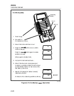
DC VOLTAGE - Select the dc voltage function and the 20V range.
Read the battery voltage by touching the probe tip from the lead
connected to the V
Ω
jack to the side contact (not the center pin) in the
opening for the battery eliminator jack on the right side of the
instrument. Be careful not to short the battery by connecting the side
contact to the center pin. Battery voltage should read 5.2V to 10V. If the
voltage is less than 5.2V, the battery should be replaced.
Warning
Do not touch the probe tips with your fingers, or allow
the probe tips to contact each other.
Local line voltage is measured in the following step:
2.
AC VOLTAGE - Select the ac voltage function and the 200V range.
Take note of the preceding warning and insert the probe tips into a
standard wall socket. The display should read the local line voltage.
Carefully remove the probe tips from the wall socket.
3.
RESISTANCE, CONTINUITY, DIODE TEST - Select the resistance
function and the 2 k
Ω
range. Touch the red (V
Ω
) probe tip to the A jack
so the V
Ω
input is shorted to the A input (this is the fuse check
procedure from section 2-4). The display should read .1000
±
.0100 k
Ω
(neglecting lead resistance).
Push the
button twice to enable the visible and audible
continuity. You should see the bar in the display and hear the tone.
Select the diode test (with the V
Ω
and A inputs still shorted together).
The display should read .0102
±
.0015V.
Remove the connection between the inputs. The instrument should
indicate OL.
Содержание 8062A
Страница 4: ......
Страница 8: ...8062A Instruction Manual iv...
Страница 10: ...8062A Instruction Manual vi...
Страница 12: ...8062A Instruction Manual viii 7 5 A1 Main PCB Schematic Diagram 7 7 7 6 A3 RMS PCB Schematic Diagram 7 8...
Страница 13: ...1 1 Chapter 1 Introduction and Specifications Contents Page 1 1 Introduction 1 3 1 2 Specifications 1 4...
Страница 14: ...8062A Instruction Manual 1 2...
Страница 24: ...8062A Instruction Manual 2 2...
Страница 50: ...8062A Instruction Manual 2 28...
Страница 52: ...8062A Instruction Manual 3 2...
Страница 62: ...8062A Instruction Manual 3 12...
Страница 64: ...8062A Instruction Manual 4 2...
Страница 90: ...8062A Instruction Manual 4 28...
Страница 92: ...8062A Instruction Manual 5 2...
Страница 97: ...List of Replaceable Parts 5 5 7 Test Button Up 1 of 2 dy37c eps Figure 5 1 8062A Final Assembly...
Страница 98: ...8062A Instruction Manual 5 8 Test Button Up 2 of 2 dy38c eps Figure 5 1 8062A Final Assembly cont...
Страница 102: ...8062A Instruction Manual 5 12 8062A 4031 iv39c eps Figure 5 2 A1 Main PCB Assembly...
Страница 106: ...8062A Instruction Manual 6 2...
Страница 108: ...8062A Instruction Manual 6 4 dy55c eps Figure 6 1 Accessories...
Страница 109: ...Accessory Information Temperature Probes 80T 150C and 80T 150F 6 6 5 dy56c eps Figure 6 1 Accessories cont...
Страница 118: ...8062A Instruction Manual 7 2...
Страница 119: ...Schematic Diagrams 7 7 3 8062A 4031 iv39c eps Figure 7 1 A1 Main PCB Component Locations TopView...
Страница 122: ...8062A Instruction Manual 7 6...
Страница 123: ...8062A Instruction Manual 7 7 8062A 1201 iu46c eps Figure 7 5 A1 Main PCB Schmatic Diagram...
Страница 124: ...8062A Instruction Manual 7 8 8060A 1003 iu61f eps Figure 7 6 A3 RMS PCB Schmatic Diagram...


