


8062A
Instruction Manual
4-12
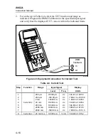
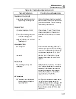
4-11. Performance Tests
The following procedures allow you to compare the performance of your
instrument with the specifications listed in Chapter 1. They are
recommended for incoming inspection, periodic calibration, and to verify
specifications. If the instrument fails any test, calibration adjustment and/or
repair is needed. You do not have to disassemble the instrument to perform
the tests. Throughout these procedures, the 8062A being tested is referred to
as the UUT (Unit Under Test).
4-12. Initial Procedure
For any of these tests, make sure you do the following:
1.
Allow the temperature of the UUT to stabilize in a test environment with
an ambient temperature of 23
±
5
°
C (73
±
9
°
F) and a relative humidity of
less than 80%
2.
Check the fuses and battery and replace them, if necessary.
3.
Make sure the leads are disconnected from the UUT. Set the power
switch to on and set all other switches to the out (off) positions.
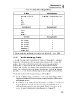
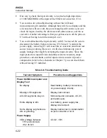
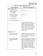
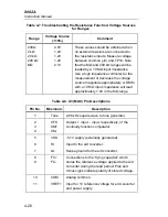
4-13. Microcomputer and Display Test
Use the automatic power-on self-test to test the microcomputer and the LCD
display. Turn the UUT off, then turn it on while observing the display. All of
the LCD segments should turn on. After about one or two seconds, the
display should go blank briefly and then respond to switch selections.
Содержание 8062A
Страница 4: ......
Страница 8: ...8062A Instruction Manual iv...
Страница 10: ...8062A Instruction Manual vi...
Страница 12: ...8062A Instruction Manual viii 7 5 A1 Main PCB Schematic Diagram 7 7 7 6 A3 RMS PCB Schematic Diagram 7 8...
Страница 13: ...1 1 Chapter 1 Introduction and Specifications Contents Page 1 1 Introduction 1 3 1 2 Specifications 1 4...
Страница 14: ...8062A Instruction Manual 1 2...
Страница 24: ...8062A Instruction Manual 2 2...
Страница 50: ...8062A Instruction Manual 2 28...
Страница 52: ...8062A Instruction Manual 3 2...
Страница 62: ...8062A Instruction Manual 3 12...
Страница 64: ...8062A Instruction Manual 4 2...
Страница 90: ...8062A Instruction Manual 4 28...
Страница 92: ...8062A Instruction Manual 5 2...
Страница 97: ...List of Replaceable Parts 5 5 7 Test Button Up 1 of 2 dy37c eps Figure 5 1 8062A Final Assembly...
Страница 98: ...8062A Instruction Manual 5 8 Test Button Up 2 of 2 dy38c eps Figure 5 1 8062A Final Assembly cont...
Страница 102: ...8062A Instruction Manual 5 12 8062A 4031 iv39c eps Figure 5 2 A1 Main PCB Assembly...
Страница 106: ...8062A Instruction Manual 6 2...
Страница 108: ...8062A Instruction Manual 6 4 dy55c eps Figure 6 1 Accessories...
Страница 109: ...Accessory Information Temperature Probes 80T 150C and 80T 150F 6 6 5 dy56c eps Figure 6 1 Accessories cont...
Страница 118: ...8062A Instruction Manual 7 2...
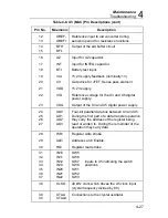
Страница 119: ...Schematic Diagrams 7 7 3 8062A 4031 iv39c eps Figure 7 1 A1 Main PCB Component Locations TopView...
Страница 122: ...8062A Instruction Manual 7 6...
Страница 123: ...8062A Instruction Manual 7 7 8062A 1201 iu46c eps Figure 7 5 A1 Main PCB Schmatic Diagram...
Страница 124: ...8062A Instruction Manual 7 8 8060A 1003 iu61f eps Figure 7 6 A3 RMS PCB Schmatic Diagram...


