


8062A
Instruction Manual
5-10
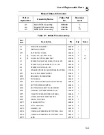
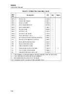
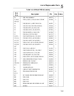
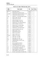
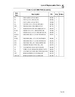
Table 5-2. A1 Main PCB Assembly (cont)
Ref.
Des
Description
PN
Qty
Notes
MP12-15
SPACER,LED .330 LG
930342
4
Q1
*
TRANSISTOR,SI,N-JFET,SEL,TO-92
721936
1
Q3,Q4,Q6
*
TRANSISTOR,SI,NPN,60V,310MW,SEL,TO-92
886916
3
Q5
*
TRANSISTOR,SI,NPN,30V,1W,TO-92
242065
1
R1,R2
RES,MF,1K,+-1%,100PPM,FLMPRF,FUSIBLE
474080
2
1
R3
RES,CC,100M,+-10%,0.5W
190520
1
R4
RES,CF,5.6K,+-5%,0.25W
442350
1
R5
RES,VAR,CERM,2K,+-20%,0.3W
603753
1
R6
RES,VAR,CERM,200,+-20%,0.3W
603738
1
R7
RES,MF,154K,+-1%,0.125W,100PPM,1206
289447
1
R8
RES,VAR,CERM,1K,+-20%,0.3W
614065
1
R10
RES,MF,3.65K,+-1%,0.25W,100PPM
810754
1
R15
RES,VAR,CERM,3K,+-20%,0.3W
689627
1
R16
RES,MF,383K,+-1%,0.125W,100PPM
288498
1
R18
RES,VAR,CERM,100,+-20%,0.3W
614057
1
R20
RES,CC,220K,+-10%,1W
109652
1
R22
RES JUMPER,0.02,0.25W
682575
1
R31
RES,CF,10,+-5%,0.25W
807669
1
R32
RES,CC,100K,+-5%,1W
641282
1
R34,R35
RES,CF,12,+-5%,0.25W
442178
2
R36
RES,CF,51K,+-5%,0.25W
376434
1
R37
RES,CF,68K,+-5%,0.25W
376632
1
RJ1-4
VARISTOR,430V,+-10%,1.0MA
447672
4
RT1
THERMISTOR,RECT.,POS.,1K,+-40%
446849
1
S1
SWITCH ASSY
535021
1
S9
SWITCH,SLIDE,SPDT,PWB,RA
453365
1
U1
DIODE BRIDGE,SI,50V,1A,DIP
418582
1
U4
*
IC,VOLTAGE CONVERTER,10.5 V MA
586248
1
VR1
ZENER,UNCOMP,6.2V,5%,20.0MA,0.4W
325811
1
VR2
*
IC, 1.22V,50 PPM T.C.,BANDGAP
508259
1
VR3
ZENER,UNCOMP,12.0V,10%,10.5MA,0.4W
741074
1
W1
WIRE,NONINSUL,JUMPER,.150CTR
643452
1
XU3
SOCKET,IC,40 PIN,DUAL WIPE,RETENTION
756668
1
Содержание 8062A
Страница 4: ......
Страница 8: ...8062A Instruction Manual iv...
Страница 10: ...8062A Instruction Manual vi...
Страница 12: ...8062A Instruction Manual viii 7 5 A1 Main PCB Schematic Diagram 7 7 7 6 A3 RMS PCB Schematic Diagram 7 8...
Страница 13: ...1 1 Chapter 1 Introduction and Specifications Contents Page 1 1 Introduction 1 3 1 2 Specifications 1 4...
Страница 14: ...8062A Instruction Manual 1 2...
Страница 24: ...8062A Instruction Manual 2 2...
Страница 50: ...8062A Instruction Manual 2 28...
Страница 52: ...8062A Instruction Manual 3 2...
Страница 62: ...8062A Instruction Manual 3 12...
Страница 64: ...8062A Instruction Manual 4 2...
Страница 90: ...8062A Instruction Manual 4 28...
Страница 92: ...8062A Instruction Manual 5 2...
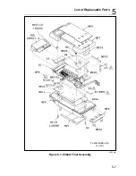
Страница 97: ...List of Replaceable Parts 5 5 7 Test Button Up 1 of 2 dy37c eps Figure 5 1 8062A Final Assembly...
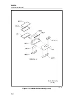
Страница 98: ...8062A Instruction Manual 5 8 Test Button Up 2 of 2 dy38c eps Figure 5 1 8062A Final Assembly cont...
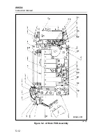
Страница 102: ...8062A Instruction Manual 5 12 8062A 4031 iv39c eps Figure 5 2 A1 Main PCB Assembly...
Страница 106: ...8062A Instruction Manual 6 2...
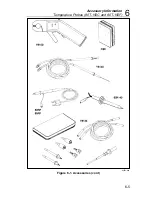
Страница 108: ...8062A Instruction Manual 6 4 dy55c eps Figure 6 1 Accessories...
Страница 109: ...Accessory Information Temperature Probes 80T 150C and 80T 150F 6 6 5 dy56c eps Figure 6 1 Accessories cont...
Страница 118: ...8062A Instruction Manual 7 2...
Страница 119: ...Schematic Diagrams 7 7 3 8062A 4031 iv39c eps Figure 7 1 A1 Main PCB Component Locations TopView...
Страница 122: ...8062A Instruction Manual 7 6...
Страница 123: ...8062A Instruction Manual 7 7 8062A 1201 iu46c eps Figure 7 5 A1 Main PCB Schmatic Diagram...
Страница 124: ...8062A Instruction Manual 7 8 8060A 1003 iu61f eps Figure 7 6 A3 RMS PCB Schmatic Diagram...


