


i
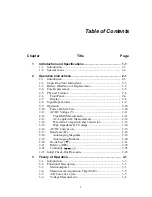
Table of Contents
Chapter
Title
Page
1
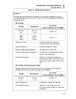
Introduction and Specifications............................................ 1-1
1-1.
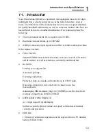
Introduction ............................................................................. 1-3
1-2.
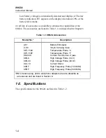
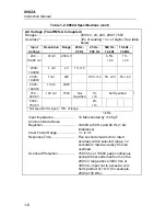
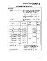
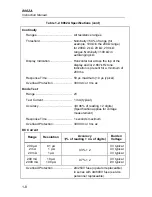
Specifications........................................................................... 1-4
2
Operation Instructions........................................................... 2-1
2-1.
Introduction ............................................................................. 2-3
2-2.
Unpacking Your Instrument..................................................... 2-3
2-3.
Battery Installation or Replacement ......................................... 2-3
2-4.
Fuse Replacement .................................................................... 2-5
2-5.
Physical Features ..................................................................... 2-6
2-6.
Front Panel........................................................................... 2-6
2-7.
Display................................................................................. 2-8
2-8.
Signal Input Limits .................................................................. 2-9
2-9.
Operation ................................................................................. 2-10
2-10.
Power-On Self-Test.............................................................. 2-10
2-11.
AC/DC Voltage (V) ............................................................. 2-11
2-12.
True RMS Measurement .................................................. 2-11
2-13.
AC-Coupled AC Measurements....................................... 2-12
2-14.
Waveform Comparison and Conversion .......................... 2-13
2-15.
High Impedance DC Voltage ........................................... 2-14
2-16.
AC/DC Current (A).............................................................. 2-15
2-17.
Resistance (
Ω
)...................................................................... 2-18
2-18.
Autoranging Megohms..................................................... 2-19
2-19.
Autoranging Kilohms....................................................... 2-20
2-20.
Diode Test (
G
)................................................................... 2-21
2-21.
Relative (REL) ..................................................................... 2-22
2-22.
Continuity (
) ........................................................... 2-25
2-23. Initial Check-Out Procedure .................................................... 2-25
3
Theory of Operation ............................................................... 3-1
3-1.
Introduction ............................................................................. 3-3
3-2.
Functional Description............................................................. 3-3
3-3.
Microcomputer..................................................................... 3-3
3-4.
Measurement Acquisition Chip (MAC) ............................... 3-5
3-5.
A/D Converter Cycle............................................................ 3-5
3-6.
Voltage Measurement .......................................................... 3-8
Содержание 8062A
Страница 4: ......
Страница 8: ...8062A Instruction Manual iv...
Страница 10: ...8062A Instruction Manual vi...
Страница 12: ...8062A Instruction Manual viii 7 5 A1 Main PCB Schematic Diagram 7 7 7 6 A3 RMS PCB Schematic Diagram 7 8...
Страница 13: ...1 1 Chapter 1 Introduction and Specifications Contents Page 1 1 Introduction 1 3 1 2 Specifications 1 4...
Страница 14: ...8062A Instruction Manual 1 2...
Страница 24: ...8062A Instruction Manual 2 2...
Страница 50: ...8062A Instruction Manual 2 28...
Страница 52: ...8062A Instruction Manual 3 2...
Страница 62: ...8062A Instruction Manual 3 12...
Страница 64: ...8062A Instruction Manual 4 2...
Страница 90: ...8062A Instruction Manual 4 28...
Страница 92: ...8062A Instruction Manual 5 2...
Страница 97: ...List of Replaceable Parts 5 5 7 Test Button Up 1 of 2 dy37c eps Figure 5 1 8062A Final Assembly...
Страница 98: ...8062A Instruction Manual 5 8 Test Button Up 2 of 2 dy38c eps Figure 5 1 8062A Final Assembly cont...
Страница 102: ...8062A Instruction Manual 5 12 8062A 4031 iv39c eps Figure 5 2 A1 Main PCB Assembly...
Страница 106: ...8062A Instruction Manual 6 2...
Страница 108: ...8062A Instruction Manual 6 4 dy55c eps Figure 6 1 Accessories...
Страница 109: ...Accessory Information Temperature Probes 80T 150C and 80T 150F 6 6 5 dy56c eps Figure 6 1 Accessories cont...
Страница 118: ...8062A Instruction Manual 7 2...
Страница 119: ...Schematic Diagrams 7 7 3 8062A 4031 iv39c eps Figure 7 1 A1 Main PCB Component Locations TopView...
Страница 122: ...8062A Instruction Manual 7 6...
Страница 123: ...8062A Instruction Manual 7 7 8062A 1201 iu46c eps Figure 7 5 A1 Main PCB Schmatic Diagram...
Страница 124: ...8062A Instruction Manual 7 8 8060A 1003 iu61f eps Figure 7 6 A3 RMS PCB Schmatic Diagram...


