


Accessory Information
Current Shunt (80J-10)
6
6-9
kHz to 700 MHz
RESPONSE.......................................
Responds to the peak value of an
input and is calibrated to read rms
value of a sine wave.
VOLTAGE RANGE .........................
0.25 to 30V rms
MAXIMUM INPUT VOLTAGE......
30V rms, 200V dc
INPUT CAPACITANCE ..................
Approximately 3 pF
TEMPERATURE RANGE
Operating.........................................
Storage ............................................
+10
°
C to +35
°
C
40
°
C to +75
°
C
HUMIDITY ......................................
<90% R.H
OUTPUT CONNECTOR..................
Fits standard 0.75-inch dual banana
connectors
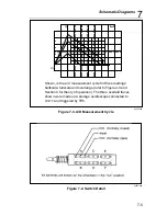
6-9. Current Shunt (80J-10)
The Model 80J-10 Current Shunt extends the current measuring capability of
the DMM to 10 amps continuous (20 amps for periods not exceeding one
minute) dc to 10 kHz at an accuracy of
±
0.25% in excess of the voltmeter
accuracy.
SHUNT .............................................
10 amps at 100 mV
ACCURACY (18
°
C to 28
°
C)
DC to 10 kHz ..................................
10 kHz to 100 kHz ..........................
±
0.25%
Rising to 1 dB at 100 kHz typical
TEMPERATURE COEFFICIENT ...
0.005%/
°
C
INDUCTANCE.................................
18.3 nH in series w/0.01
Ω
shunt
OVERLOAD.....................................
Up to one minute at 20A with a 1/4
duty cycle for recovery after currents
between 10A and 20A.
CONNECTS TO ...............................
3/4 inch center banana jacks
CONNECTORS ................................
5-way binding posts (red and black)
6-10. AC/DC Current Probe (Y8100)
The Fluke Y8100 AC/DC Current Probe is a clamp-on probe that is used
with a voltmeter, multimeter, or oscilloscope to read dc, ac or composite (ac
on dc) current measurements. The jaws on the Y8100 are designed to clamp
Содержание 8062A
Страница 4: ......
Страница 8: ...8062A Instruction Manual iv...
Страница 10: ...8062A Instruction Manual vi...
Страница 12: ...8062A Instruction Manual viii 7 5 A1 Main PCB Schematic Diagram 7 7 7 6 A3 RMS PCB Schematic Diagram 7 8...
Страница 13: ...1 1 Chapter 1 Introduction and Specifications Contents Page 1 1 Introduction 1 3 1 2 Specifications 1 4...
Страница 14: ...8062A Instruction Manual 1 2...
Страница 24: ...8062A Instruction Manual 2 2...
Страница 50: ...8062A Instruction Manual 2 28...
Страница 52: ...8062A Instruction Manual 3 2...
Страница 62: ...8062A Instruction Manual 3 12...
Страница 64: ...8062A Instruction Manual 4 2...
Страница 90: ...8062A Instruction Manual 4 28...
Страница 92: ...8062A Instruction Manual 5 2...
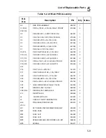
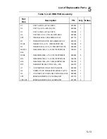
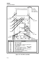
Страница 97: ...List of Replaceable Parts 5 5 7 Test Button Up 1 of 2 dy37c eps Figure 5 1 8062A Final Assembly...
Страница 98: ...8062A Instruction Manual 5 8 Test Button Up 2 of 2 dy38c eps Figure 5 1 8062A Final Assembly cont...
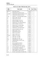
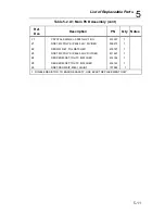
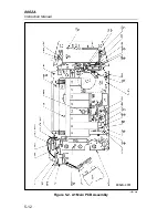
Страница 102: ...8062A Instruction Manual 5 12 8062A 4031 iv39c eps Figure 5 2 A1 Main PCB Assembly...
Страница 106: ...8062A Instruction Manual 6 2...
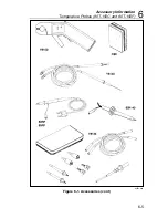
Страница 108: ...8062A Instruction Manual 6 4 dy55c eps Figure 6 1 Accessories...
Страница 109: ...Accessory Information Temperature Probes 80T 150C and 80T 150F 6 6 5 dy56c eps Figure 6 1 Accessories cont...
Страница 118: ...8062A Instruction Manual 7 2...
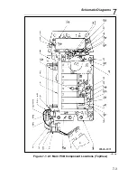
Страница 119: ...Schematic Diagrams 7 7 3 8062A 4031 iv39c eps Figure 7 1 A1 Main PCB Component Locations TopView...
Страница 122: ...8062A Instruction Manual 7 6...
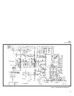
Страница 123: ...8062A Instruction Manual 7 7 8062A 1201 iu46c eps Figure 7 5 A1 Main PCB Schmatic Diagram...
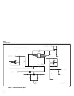
Страница 124: ...8062A Instruction Manual 7 8 8060A 1003 iu61f eps Figure 7 6 A3 RMS PCB Schmatic Diagram...


