


8062A
Instruction Manual
4-18
1.
Allow the UUT to stabilize with the power off for at least 30 minutes at
an ambient temperature of 21 to 25
°
C (70 to 77
°
F).
2.
Complete the calibration access procedure presented earlier in this
chapter.
3.
Connect the equipment as shown in Figure 4-4 and turn on the
equipment.
4.
On the UUT, select the dc voltage function and the 2 volt range. Turn
R6 fully clockwise (CW), and turn R5 fully counterclockwise (CCW).
5.
Program the DMM Calibrator for an input of 1.9000V dc. Adjust R5 for
a display reading slightly greater than 1.9000. Adjust R6 for a display
reading between 1.8999 and 1.9001.
6.
On the UUT, select the 200 mV range (dc voltage function).
7.
Program the DMM Calibrator for an input of 190.00 mV dc. Adjust R8
for a display reading between 189.99 and 190.01.
8.
On the UUT, select the ac voltage function and the 200 mV range. Turn
R18 full CW and turn R15 fully CCW.
9.
Program the DMM Calibrator for an input of 100.00 mV ac at 200 Hz.
Adjust R15 for a display reading slightly greater than 100.00. Adjust
R18 for a display reading between 99.95 and 100.05.
10.
On the UUT, select the 200V range (ac voltage function). Program the
DMM Calibrator for an input of 100.00V ac at 10 kHz. Adjust C3 until
the display reading is between .9990 and 1.0010.
11.
On the UUT, select the 2V range (ac voltage function). Program the
DMM Calibrator for an input of 1.0000V ac at 10 kHz. Adjust C7 until
the display reading is between 0.9990 and 1.0010.
12.
Steps 10 and 11 interact. Repeat both steps until the appropriate limits
are obtained for both steps.
Содержание 8062A
Страница 4: ......
Страница 8: ...8062A Instruction Manual iv...
Страница 10: ...8062A Instruction Manual vi...
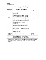
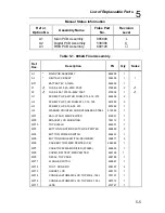
Страница 12: ...8062A Instruction Manual viii 7 5 A1 Main PCB Schematic Diagram 7 7 7 6 A3 RMS PCB Schematic Diagram 7 8...
Страница 13: ...1 1 Chapter 1 Introduction and Specifications Contents Page 1 1 Introduction 1 3 1 2 Specifications 1 4...
Страница 14: ...8062A Instruction Manual 1 2...
Страница 24: ...8062A Instruction Manual 2 2...
Страница 50: ...8062A Instruction Manual 2 28...
Страница 52: ...8062A Instruction Manual 3 2...
Страница 62: ...8062A Instruction Manual 3 12...
Страница 64: ...8062A Instruction Manual 4 2...
Страница 90: ...8062A Instruction Manual 4 28...
Страница 92: ...8062A Instruction Manual 5 2...
Страница 97: ...List of Replaceable Parts 5 5 7 Test Button Up 1 of 2 dy37c eps Figure 5 1 8062A Final Assembly...
Страница 98: ...8062A Instruction Manual 5 8 Test Button Up 2 of 2 dy38c eps Figure 5 1 8062A Final Assembly cont...
Страница 102: ...8062A Instruction Manual 5 12 8062A 4031 iv39c eps Figure 5 2 A1 Main PCB Assembly...
Страница 106: ...8062A Instruction Manual 6 2...
Страница 108: ...8062A Instruction Manual 6 4 dy55c eps Figure 6 1 Accessories...
Страница 109: ...Accessory Information Temperature Probes 80T 150C and 80T 150F 6 6 5 dy56c eps Figure 6 1 Accessories cont...
Страница 118: ...8062A Instruction Manual 7 2...
Страница 119: ...Schematic Diagrams 7 7 3 8062A 4031 iv39c eps Figure 7 1 A1 Main PCB Component Locations TopView...
Страница 122: ...8062A Instruction Manual 7 6...
Страница 123: ...8062A Instruction Manual 7 7 8062A 1201 iu46c eps Figure 7 5 A1 Main PCB Schmatic Diagram...
Страница 124: ...8062A Instruction Manual 7 8 8060A 1003 iu61f eps Figure 7 6 A3 RMS PCB Schmatic Diagram...


