


Accessory Information
Introduction
6
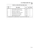
6-3
6-1. Introduction
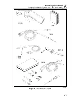
This chapter of the manual contains information concerning the accessories
available of use with your multimeter. Each accessory, as shown in Figure 6-
1, is described in general terms under a separate major heading containing
the accessory model number. The depth of detail is intended to give the
prospective user an adequate first acquaintance with the features and
capabilities of each accessory. Additional information, when necessary, is
supplied with the accessory.
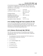
6-2. Deluxe Carrying Case (C90)
The C90 Deluxe Carrying Case is a pliable, vinyl, zipper-closed pouch that
provides in-field-transport protection for the instrument as well as convenient
storage locations for test leads, operator guide and other small accessories. A
finger- or belt-loop is included on the case as a carrying convenience.
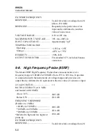
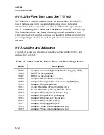
6-3. Temperature Probes (80T-150C and 80T-
150F)
The 80T-150 Temperature Probe coverts the instrument into a direct-reading
(1 mV dc/
°
)
°
C (80T-150C) or F
°
(80T-150F) thermometer. It is ideally
suited for surface, ambient, and liquid measurements and lends itself easily
to a wide range of design, troubleshooting, and evaluation applications. A
rugged, fast-responding probe-tip with a 350V dc standoff makes the 80T-
150 one of the most versatile and easy-to-use temperature probes available.
RANGE (
°
C/
°
F)
80T-150C ........................................
80T-150f .........................................
-50
°
C to +150
°
C
-58
°
F to 302
°
F
ACCURACY.....................................
±
1
°
C (1.8
°
F) from 0
°
C to 100
°
C,
decreasing linearly to
±
3
°
C (5.4
°
F)
at -50
°
C and +150
°
C
VOLTAGE STANDOFF ..................
350V dc or peak ac
POWER.............................................
Internal disposable battery; 1,000
hours of continuous use.
Содержание 8062A
Страница 4: ......
Страница 8: ...8062A Instruction Manual iv...
Страница 10: ...8062A Instruction Manual vi...
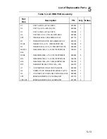
Страница 12: ...8062A Instruction Manual viii 7 5 A1 Main PCB Schematic Diagram 7 7 7 6 A3 RMS PCB Schematic Diagram 7 8...
Страница 13: ...1 1 Chapter 1 Introduction and Specifications Contents Page 1 1 Introduction 1 3 1 2 Specifications 1 4...
Страница 14: ...8062A Instruction Manual 1 2...
Страница 24: ...8062A Instruction Manual 2 2...
Страница 50: ...8062A Instruction Manual 2 28...
Страница 52: ...8062A Instruction Manual 3 2...
Страница 62: ...8062A Instruction Manual 3 12...
Страница 64: ...8062A Instruction Manual 4 2...
Страница 90: ...8062A Instruction Manual 4 28...
Страница 92: ...8062A Instruction Manual 5 2...
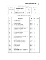
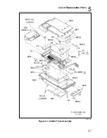
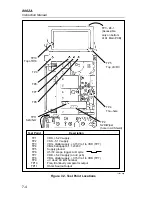
Страница 97: ...List of Replaceable Parts 5 5 7 Test Button Up 1 of 2 dy37c eps Figure 5 1 8062A Final Assembly...
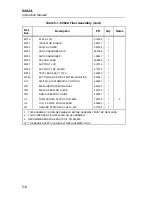
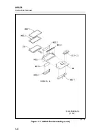
Страница 98: ...8062A Instruction Manual 5 8 Test Button Up 2 of 2 dy38c eps Figure 5 1 8062A Final Assembly cont...
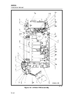
Страница 102: ...8062A Instruction Manual 5 12 8062A 4031 iv39c eps Figure 5 2 A1 Main PCB Assembly...
Страница 106: ...8062A Instruction Manual 6 2...
Страница 108: ...8062A Instruction Manual 6 4 dy55c eps Figure 6 1 Accessories...
Страница 109: ...Accessory Information Temperature Probes 80T 150C and 80T 150F 6 6 5 dy56c eps Figure 6 1 Accessories cont...
Страница 118: ...8062A Instruction Manual 7 2...
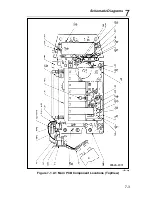
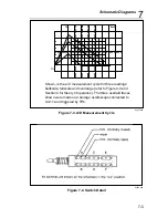
Страница 119: ...Schematic Diagrams 7 7 3 8062A 4031 iv39c eps Figure 7 1 A1 Main PCB Component Locations TopView...
Страница 122: ...8062A Instruction Manual 7 6...
Страница 123: ...8062A Instruction Manual 7 7 8062A 1201 iu46c eps Figure 7 5 A1 Main PCB Schmatic Diagram...
Страница 124: ...8062A Instruction Manual 7 8 8060A 1003 iu61f eps Figure 7 6 A3 RMS PCB Schmatic Diagram...


