


8062A
Instruction Manual
4-4
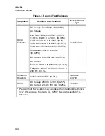
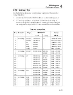
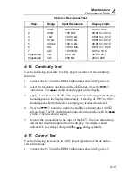
Table 4-1. Required Test Equipment
Equipment
Required specifications
Recommended
Type
DMM
Calibrator
DC Voltage: 0 to 1000V,
±
(0.0075%)
AC Voltage:
200 Hz to 1 kHz, 0 to 750V,
±
(0.06%)
1 kHz to 10 kHz, 0 to 200 V,
±
(0.06%)
10 kHz to 30 kHz, 0 to 200V,
±
(0.1%)
30 kHz to 50 kHz, 0 to 200V,
±
(0.25%)
50 kHz to 100 kHz, 0 to 2.0V,
±
(0.75%)
Resistance: 100
Ω
to 10.0 M
Ω
,
±
(0.025%)
Fluke 5700A
DC Current: 0 to 2000 mA,
±
(0.075%)
AC Current:
20 Hz to 3 kHz, 0 to 2000 mA,
±
(0.18%)
Frequency: 25 mV to 200 mV, 100 Hz to
200 kHz,
±
(0.1%)
Reference
Resistors
40 M
Ω
and 290 M
Ω
,
±
(0.1%)
Caddock
MG750*
DMM
DC Voltage: 200 mV to 20V,
±
(0.25%)
DC Current: 2 mA to 200 mA,
±
(0.25%)
Fluke 87
* Precision high M
Ω
resistors may be ordered from Caddock Electronics,
3127 Chicago Ave., Riverside, CA, 92507. Be sure to specify 0.1%
tolerance.
Содержание 8062A
Страница 4: ......
Страница 8: ...8062A Instruction Manual iv...
Страница 10: ...8062A Instruction Manual vi...
Страница 12: ...8062A Instruction Manual viii 7 5 A1 Main PCB Schematic Diagram 7 7 7 6 A3 RMS PCB Schematic Diagram 7 8...
Страница 13: ...1 1 Chapter 1 Introduction and Specifications Contents Page 1 1 Introduction 1 3 1 2 Specifications 1 4...
Страница 14: ...8062A Instruction Manual 1 2...
Страница 24: ...8062A Instruction Manual 2 2...
Страница 50: ...8062A Instruction Manual 2 28...
Страница 52: ...8062A Instruction Manual 3 2...
Страница 62: ...8062A Instruction Manual 3 12...
Страница 64: ...8062A Instruction Manual 4 2...
Страница 90: ...8062A Instruction Manual 4 28...
Страница 92: ...8062A Instruction Manual 5 2...
Страница 97: ...List of Replaceable Parts 5 5 7 Test Button Up 1 of 2 dy37c eps Figure 5 1 8062A Final Assembly...
Страница 98: ...8062A Instruction Manual 5 8 Test Button Up 2 of 2 dy38c eps Figure 5 1 8062A Final Assembly cont...
Страница 102: ...8062A Instruction Manual 5 12 8062A 4031 iv39c eps Figure 5 2 A1 Main PCB Assembly...
Страница 106: ...8062A Instruction Manual 6 2...
Страница 108: ...8062A Instruction Manual 6 4 dy55c eps Figure 6 1 Accessories...
Страница 109: ...Accessory Information Temperature Probes 80T 150C and 80T 150F 6 6 5 dy56c eps Figure 6 1 Accessories cont...
Страница 118: ...8062A Instruction Manual 7 2...
Страница 119: ...Schematic Diagrams 7 7 3 8062A 4031 iv39c eps Figure 7 1 A1 Main PCB Component Locations TopView...
Страница 122: ...8062A Instruction Manual 7 6...
Страница 123: ...8062A Instruction Manual 7 7 8062A 1201 iu46c eps Figure 7 5 A1 Main PCB Schmatic Diagram...
Страница 124: ...8062A Instruction Manual 7 8 8060A 1003 iu61f eps Figure 7 6 A3 RMS PCB Schmatic Diagram...


