


Maintenance
Troubleshooting
4
4-23
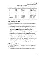
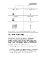
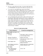
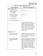
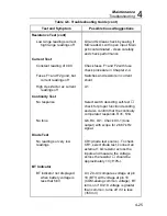
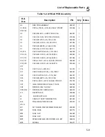
Table 4-6. Troubleshooting Guide (cont)
Test and Symptom
Possible Cause/Suggestions
Power Supply (cont)
VDG (voltage between
TP7 and TP8)
≠
3.15
±
0.08V
U3, C12, U5
VSS (voltage between
TP2 and common)
≠
-5.1
±
0.27V
U4, C21, C23
TP4
≠
1.225
±
0.025V
U3-11
≠
1.0000
±
0.0004V
Hint: if you suspect U3 power
supplies are bad, you can drive the
8062A power supplies externally.
Remove battery,
µ
C pcb, and U3.
Apply +5.2V at TP1
you can then
check the ac converter, diode test
source, VR2, U4, and the power
supply circuitry.
Voltage Test - DC
Gross error (constant
reading of 0.00 or OL)
Perform ratio self-test in dc volts. If
count is good, U3 is good. If count is
way off, suspect U3, C9, R33, R8,
Z3, C16 or C18
Ratio self-test passes,
but constant reading
of 0.00
R1, R2 (fusible resistors
replace
with exact equivalent only). RJ1, RJ2,
RJ3, RJ4 (varstors turn yellow when
shorted), open circuit in front end,
bad component is input divider, U3
pins 6 and 7 shorted. (Hint: check
high impedance dc voltage first,
which bypasses the input divider.)
Refer to Table 4-1 for input divide
ratios.
Содержание 8062A
Страница 4: ......
Страница 8: ...8062A Instruction Manual iv...
Страница 10: ...8062A Instruction Manual vi...
Страница 12: ...8062A Instruction Manual viii 7 5 A1 Main PCB Schematic Diagram 7 7 7 6 A3 RMS PCB Schematic Diagram 7 8...
Страница 13: ...1 1 Chapter 1 Introduction and Specifications Contents Page 1 1 Introduction 1 3 1 2 Specifications 1 4...
Страница 14: ...8062A Instruction Manual 1 2...
Страница 24: ...8062A Instruction Manual 2 2...
Страница 50: ...8062A Instruction Manual 2 28...
Страница 52: ...8062A Instruction Manual 3 2...
Страница 62: ...8062A Instruction Manual 3 12...
Страница 64: ...8062A Instruction Manual 4 2...
Страница 90: ...8062A Instruction Manual 4 28...
Страница 92: ...8062A Instruction Manual 5 2...
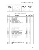
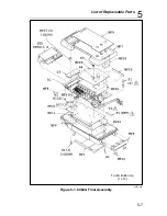
Страница 97: ...List of Replaceable Parts 5 5 7 Test Button Up 1 of 2 dy37c eps Figure 5 1 8062A Final Assembly...
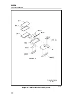
Страница 98: ...8062A Instruction Manual 5 8 Test Button Up 2 of 2 dy38c eps Figure 5 1 8062A Final Assembly cont...
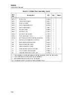
Страница 102: ...8062A Instruction Manual 5 12 8062A 4031 iv39c eps Figure 5 2 A1 Main PCB Assembly...
Страница 106: ...8062A Instruction Manual 6 2...
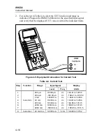
Страница 108: ...8062A Instruction Manual 6 4 dy55c eps Figure 6 1 Accessories...
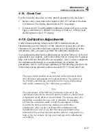
Страница 109: ...Accessory Information Temperature Probes 80T 150C and 80T 150F 6 6 5 dy56c eps Figure 6 1 Accessories cont...
Страница 118: ...8062A Instruction Manual 7 2...
Страница 119: ...Schematic Diagrams 7 7 3 8062A 4031 iv39c eps Figure 7 1 A1 Main PCB Component Locations TopView...
Страница 122: ...8062A Instruction Manual 7 6...
Страница 123: ...8062A Instruction Manual 7 7 8062A 1201 iu46c eps Figure 7 5 A1 Main PCB Schmatic Diagram...
Страница 124: ...8062A Instruction Manual 7 8 8060A 1003 iu61f eps Figure 7 6 A3 RMS PCB Schmatic Diagram...


