Operation Instructions
Operation
2
2-23
For example, if a reading of 1.0000V dc is displayed when the REL button is
pressed, (the display will read 0.0000 after REL is pressed), subsequent
readings will have 1.0000 subtracted from them. If the next measurement is
1.2700V dc, the reading displayed will be .2700. If the next measurement is
0.8500V dc, the reading displayed will be -.1500. You may cancel the
relative reference by pressing the REL button (the REL indicator disappears
from the display), by turning the instrument off, or by storing a relative
reference with another function.
If you change ranges, the relative reference is automatically multiplied or
divided by the appropriate power of ten before being subtracted from the
measurement. If you change functions, the REL indicator disappears and the
relative reference is stored with the original function. When you reselect the
function, the relative reference is restored (the REL indicator reappears)
unless a new relative reference was established in another function.
The relative function may be used with all the measurement functions: ac or
dc voltage, ac or dc current, resistance, and diode test. When used with
continuity, the relative function stores the accompanying resistance readings.
Note that the input overload limits are not affected by the use of the relative
function.
Another thing to be aware of when using relative reference is that the range
of possible readings is still subject to the limits of the display and the 19999
counts of the analog-to-digital (a/d) converter, regardless of the relative
reference. For example, suppose the instrument is in the dc voltage function
with the 20V range selected, and you store a relative reference of 15V. The
maximum positive voltage reading that can be displayed without overranging
is 4.999V, which is actually a 19.999V input signal. Any input signal greater
than 4.999V exceeds the 19999 counts of the a/d converter. The minimum
(negative) voltage reading that may be displayed without overranging is -
19.999V, which is a -4.999V input signal. Any input signal less that -4.999V
causes an overrange (indicated by OL on the display) because the display has
reached negative full-scale. You can avoid this situation by selecting a higher
range.
Remember that even though the REL indicator appears on the display almost
instantaneously after the REL button is pressed, the relative reference is not
stored until the next measurement takes place. For all functions, the time
between measurements is about 0.4 seconds.
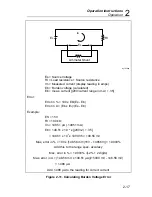
A typical way to use the relative reference is to correct for test lead
resistance. Although test lead resistance is usually very small (typically two
or three
Ω
), it can be significant when measuring low resistances. To correct
Содержание 8062A
Страница 4: ......
Страница 8: ...8062A Instruction Manual iv...
Страница 10: ...8062A Instruction Manual vi...
Страница 12: ...8062A Instruction Manual viii 7 5 A1 Main PCB Schematic Diagram 7 7 7 6 A3 RMS PCB Schematic Diagram 7 8...
Страница 13: ...1 1 Chapter 1 Introduction and Specifications Contents Page 1 1 Introduction 1 3 1 2 Specifications 1 4...
Страница 14: ...8062A Instruction Manual 1 2...
Страница 24: ...8062A Instruction Manual 2 2...
Страница 50: ...8062A Instruction Manual 2 28...
Страница 52: ...8062A Instruction Manual 3 2...
Страница 62: ...8062A Instruction Manual 3 12...
Страница 64: ...8062A Instruction Manual 4 2...
Страница 90: ...8062A Instruction Manual 4 28...
Страница 92: ...8062A Instruction Manual 5 2...
Страница 97: ...List of Replaceable Parts 5 5 7 Test Button Up 1 of 2 dy37c eps Figure 5 1 8062A Final Assembly...
Страница 98: ...8062A Instruction Manual 5 8 Test Button Up 2 of 2 dy38c eps Figure 5 1 8062A Final Assembly cont...
Страница 102: ...8062A Instruction Manual 5 12 8062A 4031 iv39c eps Figure 5 2 A1 Main PCB Assembly...
Страница 106: ...8062A Instruction Manual 6 2...
Страница 108: ...8062A Instruction Manual 6 4 dy55c eps Figure 6 1 Accessories...
Страница 109: ...Accessory Information Temperature Probes 80T 150C and 80T 150F 6 6 5 dy56c eps Figure 6 1 Accessories cont...
Страница 118: ...8062A Instruction Manual 7 2...
Страница 119: ...Schematic Diagrams 7 7 3 8062A 4031 iv39c eps Figure 7 1 A1 Main PCB Component Locations TopView...
Страница 122: ...8062A Instruction Manual 7 6...
Страница 123: ...8062A Instruction Manual 7 7 8062A 1201 iu46c eps Figure 7 5 A1 Main PCB Schmatic Diagram...
Страница 124: ...8062A Instruction Manual 7 8 8060A 1003 iu61f eps Figure 7 6 A3 RMS PCB Schmatic Diagram...

