Maintenance
General Information
4
4-11
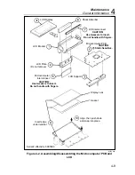
To disassemble the microcomputer pcb, use the following procedure:
1.
Turn the main pcb face down and remove the two small screws at the
top of the pcb to free the microcomputer pcb.
2.
Refer to Figure 4-2. Beginning with item 7, remove items 7 through 3
(leave item 2 attached to item 1). Be sure to observe the handling
precautions for items 7, 5, and 4.
To assemble the microcomputer LCD, refer to Figure 4-2. Beginning with
item 3, assemble items 3 through 7 (in ascending numerical order). Be sure
to follow the handling precautions for items 4, 5, and 7.
4-9.
Backup Fuse Replacement
Use the following procedure to replace the backup fuse (F2):
1.
Remove the top cover by following the precautions given previously for
the calibration and backup fuse access.
2.
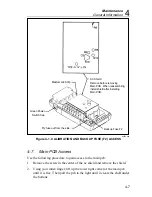
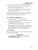
Use a flat-tipped screwdriver to pry the fuse out of its fuse holder. Pry
the fuse from the side as indicated in Figure 4-1.
3.
Replace the defective backup fuse with a 3A/600V type BBS-3 (Fluke
PN 475004). Refer to section 2-4 for information about replacing fuse
F1 (2A/250V; American style: fast acting type AGX2 1/4 x 1”, Fluke
PN 376582; European style: 5 x 20 mm, Fluke PN 460972).
4-10. Cleaning
Clean the front panel and case with a damp cloth and mild detergent. Do not
use abrasives, solvents, or alcohol.
Warning
To avoid electrical shock, remove test leads and any
input signals before cleaning.
Содержание 8062A
Страница 4: ......
Страница 8: ...8062A Instruction Manual iv...
Страница 10: ...8062A Instruction Manual vi...
Страница 12: ...8062A Instruction Manual viii 7 5 A1 Main PCB Schematic Diagram 7 7 7 6 A3 RMS PCB Schematic Diagram 7 8...
Страница 13: ...1 1 Chapter 1 Introduction and Specifications Contents Page 1 1 Introduction 1 3 1 2 Specifications 1 4...
Страница 14: ...8062A Instruction Manual 1 2...
Страница 24: ...8062A Instruction Manual 2 2...
Страница 50: ...8062A Instruction Manual 2 28...
Страница 52: ...8062A Instruction Manual 3 2...
Страница 62: ...8062A Instruction Manual 3 12...
Страница 64: ...8062A Instruction Manual 4 2...
Страница 90: ...8062A Instruction Manual 4 28...
Страница 92: ...8062A Instruction Manual 5 2...
Страница 97: ...List of Replaceable Parts 5 5 7 Test Button Up 1 of 2 dy37c eps Figure 5 1 8062A Final Assembly...
Страница 98: ...8062A Instruction Manual 5 8 Test Button Up 2 of 2 dy38c eps Figure 5 1 8062A Final Assembly cont...
Страница 102: ...8062A Instruction Manual 5 12 8062A 4031 iv39c eps Figure 5 2 A1 Main PCB Assembly...
Страница 106: ...8062A Instruction Manual 6 2...
Страница 108: ...8062A Instruction Manual 6 4 dy55c eps Figure 6 1 Accessories...
Страница 109: ...Accessory Information Temperature Probes 80T 150C and 80T 150F 6 6 5 dy56c eps Figure 6 1 Accessories cont...
Страница 118: ...8062A Instruction Manual 7 2...
Страница 119: ...Schematic Diagrams 7 7 3 8062A 4031 iv39c eps Figure 7 1 A1 Main PCB Component Locations TopView...
Страница 122: ...8062A Instruction Manual 7 6...
Страница 123: ...8062A Instruction Manual 7 7 8062A 1201 iu46c eps Figure 7 5 A1 Main PCB Schmatic Diagram...
Страница 124: ...8062A Instruction Manual 7 8 8060A 1003 iu61f eps Figure 7 6 A3 RMS PCB Schmatic Diagram...

