List of Replaceable Parts
5
5-5
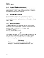
Manual Status Information
Ref or
Option No.
Assembly Name
Fluke Part
No.
Revision
Level
A1
A2
A3
Main PCB Assembly
Digital PCB Assembly
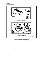
RMS PCB Assembly
865808
538306
609120
L
C
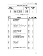
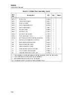
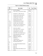
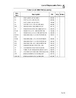
Table 5-1. 8062A Final Assembly
Ref.
Des.
Description
PN
Qty
Notes
A1
*
MAIN PCB ASSEMBLY
865808
1
A2
*
DIGITAL PCB ASSY
538306
1
1
BT1
BATTERY,9V,0-15MA
696534
1
F1
W
FUSE,.25X1.0,2A,250V,FAST
376582
2
W
F2
W
FUSE,.406,1.375,3A,600V,FAST
475004
1
W
H1
SCREW,PH,P,AM THD FORM,STL,4-14./375
448456
2
H2
SCREW,PH,P,THD FORM,STL,7-19,.750
447953
3
H3
SCREW,FH,P,STL,6-32,.375
837682
1
H4
WASHER,COUNTER SUNK,STAINLESS STEEL
614529
1
MP1
BAIL-STAND, MED PEWTER
616961
1
MP2
BRACKET,LCD MOUNTING
795112
1
MP10
TOP SHIELD
604801
1
MP3
BUTTON,FUNCTION SWITCH-DK PEWTER
606889
3
MP4
BUTTON, POWER SWITCH
456491
1
MP5
BUTTON,RANGE SWITCH-DK UMBER
606871
5
MP6
CASE,BOTTOM, MED PEWTER (CE)
664984
1
MP7
CASE,TOP 8060A MODIFIED (573980)
638635
1
MP8
COVER, BATTERY,MED PEWTER
649126
1
MP9
DECAL, TOP CASE
604785
1
MP11
FLANGE, SWITCH
455881
1
MP12
FOOT, NON-SKID
604397
4
MP13
GASKET, LCD
605170
1
MP14
CONN,ELASTOMERIC,LCD TO PWB,2..153 L
783191
1
MP15
CONN,ELASTOMERIC,LCD TO PWB,2.153 L
587014
1
MP17
LENS
612747
1
Содержание 8062A
Страница 4: ......
Страница 8: ...8062A Instruction Manual iv...
Страница 10: ...8062A Instruction Manual vi...
Страница 12: ...8062A Instruction Manual viii 7 5 A1 Main PCB Schematic Diagram 7 7 7 6 A3 RMS PCB Schematic Diagram 7 8...
Страница 13: ...1 1 Chapter 1 Introduction and Specifications Contents Page 1 1 Introduction 1 3 1 2 Specifications 1 4...
Страница 14: ...8062A Instruction Manual 1 2...
Страница 24: ...8062A Instruction Manual 2 2...
Страница 50: ...8062A Instruction Manual 2 28...
Страница 52: ...8062A Instruction Manual 3 2...
Страница 62: ...8062A Instruction Manual 3 12...
Страница 64: ...8062A Instruction Manual 4 2...
Страница 90: ...8062A Instruction Manual 4 28...
Страница 92: ...8062A Instruction Manual 5 2...
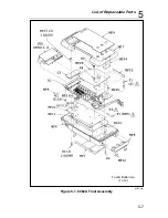
Страница 97: ...List of Replaceable Parts 5 5 7 Test Button Up 1 of 2 dy37c eps Figure 5 1 8062A Final Assembly...
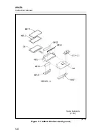
Страница 98: ...8062A Instruction Manual 5 8 Test Button Up 2 of 2 dy38c eps Figure 5 1 8062A Final Assembly cont...
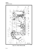
Страница 102: ...8062A Instruction Manual 5 12 8062A 4031 iv39c eps Figure 5 2 A1 Main PCB Assembly...
Страница 106: ...8062A Instruction Manual 6 2...
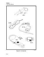
Страница 108: ...8062A Instruction Manual 6 4 dy55c eps Figure 6 1 Accessories...
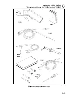
Страница 109: ...Accessory Information Temperature Probes 80T 150C and 80T 150F 6 6 5 dy56c eps Figure 6 1 Accessories cont...
Страница 118: ...8062A Instruction Manual 7 2...
Страница 119: ...Schematic Diagrams 7 7 3 8062A 4031 iv39c eps Figure 7 1 A1 Main PCB Component Locations TopView...
Страница 122: ...8062A Instruction Manual 7 6...
Страница 123: ...8062A Instruction Manual 7 7 8062A 1201 iu46c eps Figure 7 5 A1 Main PCB Schmatic Diagram...
Страница 124: ...8062A Instruction Manual 7 8 8060A 1003 iu61f eps Figure 7 6 A3 RMS PCB Schmatic Diagram...

