8062A
Instruction Manual
4-8
Caution
Do not touch or contaminate the plastic insulator that is
attached to the inside of the case bottom. When the
instrument is assembled the insulator makes contact
with the leads on the bottom of the main pcb.
Contaminants could cause undesirable conduction
paths. If the insulator becomes contaminated, clean with
isopropyl alcohol.
3.
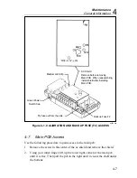
Reassemble in the logical reverse order and heed the following notes:
a.
When reassembling, be sure to put on the ac shield after the main
pcb has been placed in the case bottom. The reason for this is that
the screw which holds down the ac shield has a spring attached. The
spring provides the electrical connection between the top of the ac
shield and the bottom of the shield (under the insulator). If the ac
shield is attached to the main pcb before the main pcb is in the case,
the spring may fold across the insulator and not be in proper
position to make the electrical connection.
b.
Be sure to place the green power switch cap over the small black
power switch before sliding the main pcb into the case.
c.
Be sure to route the battery-clip wires to the left side of the post
under the backup fuse case.
4-8.
LCD and Microcomputer PCB Disassembly and
Assembly
Note
This procedure applies to models with s/n 4025xxx and higher.
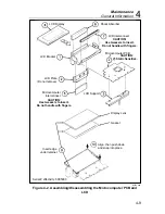
The procedure for disassembling or assembling the LCD and the
microcomputer pcb is not difficult, but the steps must be followed in
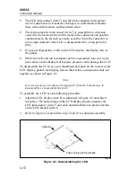
sequence. Before you try the procedure, examine the components in Figure
4-2 and familiarize yourself with the following handling precautions:
•
The microcomputer, U5 (item 4 in Figure 4-2), is a static sensitive
CMOS device. Follow standard procedures for handling static sensitive
devices.
Содержание 8062A
Страница 4: ......
Страница 8: ...8062A Instruction Manual iv...
Страница 10: ...8062A Instruction Manual vi...
Страница 12: ...8062A Instruction Manual viii 7 5 A1 Main PCB Schematic Diagram 7 7 7 6 A3 RMS PCB Schematic Diagram 7 8...
Страница 13: ...1 1 Chapter 1 Introduction and Specifications Contents Page 1 1 Introduction 1 3 1 2 Specifications 1 4...
Страница 14: ...8062A Instruction Manual 1 2...
Страница 24: ...8062A Instruction Manual 2 2...
Страница 50: ...8062A Instruction Manual 2 28...
Страница 52: ...8062A Instruction Manual 3 2...
Страница 62: ...8062A Instruction Manual 3 12...
Страница 64: ...8062A Instruction Manual 4 2...
Страница 90: ...8062A Instruction Manual 4 28...
Страница 92: ...8062A Instruction Manual 5 2...
Страница 97: ...List of Replaceable Parts 5 5 7 Test Button Up 1 of 2 dy37c eps Figure 5 1 8062A Final Assembly...
Страница 98: ...8062A Instruction Manual 5 8 Test Button Up 2 of 2 dy38c eps Figure 5 1 8062A Final Assembly cont...
Страница 102: ...8062A Instruction Manual 5 12 8062A 4031 iv39c eps Figure 5 2 A1 Main PCB Assembly...
Страница 106: ...8062A Instruction Manual 6 2...
Страница 108: ...8062A Instruction Manual 6 4 dy55c eps Figure 6 1 Accessories...
Страница 109: ...Accessory Information Temperature Probes 80T 150C and 80T 150F 6 6 5 dy56c eps Figure 6 1 Accessories cont...
Страница 118: ...8062A Instruction Manual 7 2...
Страница 119: ...Schematic Diagrams 7 7 3 8062A 4031 iv39c eps Figure 7 1 A1 Main PCB Component Locations TopView...
Страница 122: ...8062A Instruction Manual 7 6...
Страница 123: ...8062A Instruction Manual 7 7 8062A 1201 iu46c eps Figure 7 5 A1 Main PCB Schmatic Diagram...
Страница 124: ...8062A Instruction Manual 7 8 8060A 1003 iu61f eps Figure 7 6 A3 RMS PCB Schmatic Diagram...

