


8062A
Instruction Manual
4-20
4-23. Switch Decoding Self-Test
To select the switch decoding self-test, hold down the REL button while you
turn on the instrument. After the power-on self-test has been completed (the
display is .8.8.8.8), release the REL button. The instrument should now
indicate the switch decoding. To cancel the switch decoding self-test, turn off
the instrument.
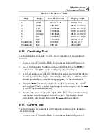
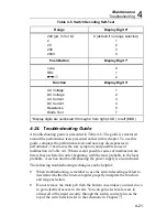
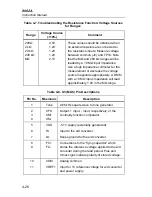
The switch decoding self-test indicates how the software in the
microcomputer interprets the configuration of the eight switches and four
push buttons. Each function or range that may be selected corresponds to a
number that appears in one of the digit positions on the display (see Table 4-
5). Notice that if no range is selected, the microcomputer assumes the 200
(
µ
A, mV,
Ω
) range is selected.
In some cases it may helpful to know that the microcomputer scans the
switches in order from SW5 to SW8 (there is no input for switch SW4, the
default range). The microcomputer assumes the first range switch detected as
being pushed in is the desired range. For example, if you press in both the
200V and 1000V switches while in dc voltage, the microcomputer assumes
you want the 200V range. There is one exception: if the microcomputer
detects that the 2 k
Ω
switch is selected, it checks for the 20 k
Ω
switch which
indicates diode test selection when pushed in.
Also during the switch decoding self-test, the continuity indicator (the long
bar across the top of the display) indicates the state of the continuity
comparator. When the voltage at U3-4 (CM-) is less than at U3-3 (CM+), the
continuity indicator is on. When the voltage at U3-4 is greater than at U3-3,
the continuity indicator is off. You can use this feature to check the
comparator when troubleshooting the continuity function. R9 controls the
setting of the comparator offset.
Содержание 8062A
Страница 4: ......
Страница 8: ...8062A Instruction Manual iv...
Страница 10: ...8062A Instruction Manual vi...
Страница 12: ...8062A Instruction Manual viii 7 5 A1 Main PCB Schematic Diagram 7 7 7 6 A3 RMS PCB Schematic Diagram 7 8...
Страница 13: ...1 1 Chapter 1 Introduction and Specifications Contents Page 1 1 Introduction 1 3 1 2 Specifications 1 4...
Страница 14: ...8062A Instruction Manual 1 2...
Страница 24: ...8062A Instruction Manual 2 2...
Страница 50: ...8062A Instruction Manual 2 28...
Страница 52: ...8062A Instruction Manual 3 2...
Страница 62: ...8062A Instruction Manual 3 12...
Страница 64: ...8062A Instruction Manual 4 2...
Страница 90: ...8062A Instruction Manual 4 28...
Страница 92: ...8062A Instruction Manual 5 2...
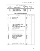
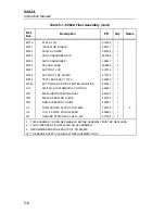
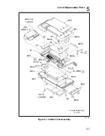
Страница 97: ...List of Replaceable Parts 5 5 7 Test Button Up 1 of 2 dy37c eps Figure 5 1 8062A Final Assembly...
Страница 98: ...8062A Instruction Manual 5 8 Test Button Up 2 of 2 dy38c eps Figure 5 1 8062A Final Assembly cont...
Страница 102: ...8062A Instruction Manual 5 12 8062A 4031 iv39c eps Figure 5 2 A1 Main PCB Assembly...
Страница 106: ...8062A Instruction Manual 6 2...
Страница 108: ...8062A Instruction Manual 6 4 dy55c eps Figure 6 1 Accessories...
Страница 109: ...Accessory Information Temperature Probes 80T 150C and 80T 150F 6 6 5 dy56c eps Figure 6 1 Accessories cont...
Страница 118: ...8062A Instruction Manual 7 2...
Страница 119: ...Schematic Diagrams 7 7 3 8062A 4031 iv39c eps Figure 7 1 A1 Main PCB Component Locations TopView...
Страница 122: ...8062A Instruction Manual 7 6...
Страница 123: ...8062A Instruction Manual 7 7 8062A 1201 iu46c eps Figure 7 5 A1 Main PCB Schmatic Diagram...
Страница 124: ...8062A Instruction Manual 7 8 8060A 1003 iu61f eps Figure 7 6 A3 RMS PCB Schmatic Diagram...


