


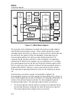


Theory of Operation
Functional Description
3
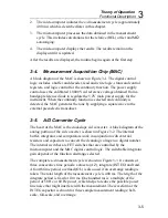
3-9
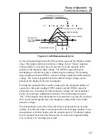
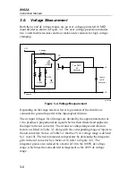
The ac input voltages are divided with the same divider arrangement as the
dc input voltages, with the exception that the 2V ac voltage range is divided
by 10. The divider output signals for ac voltages are ac-coupled to the input
of a true rms ac converter which produces a current output. A negative dc
representation of the ac input signal is filtered and applied to the input of the
a/d converter.
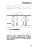
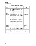
Table 3-1. Voltage Input Divider
Function
Range
Input
Divider
Range of A/D Converter Input
DC Voltage
200 mV
2V*
20V
200V
1000V*
1/1
1/1
1/100
1/1000
1/1000
-200 mV to +200 mV
-2V to +2V
-200 mV to +200 mV
-200 mV to +200 mV
-2V to + 2V (1V max. input)
AC Voltage
200 mV
2V
20V
200V
750V*
1/1
1/10
1/100
1/1000
1/1000
0 to -200 mV
0 to -200 mV
0 to -200 mV
0 to -200 mV
0 to -2V (-0.75V max. input)
*Integrator gain in a/d converter reduced by factor of 10.
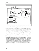
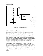
3-7. Current
Measurement
Current measurements are made using a double-fuse-protected, switchable,
five-terminal current shunt (0.1 ohm, 1 ohm, 10 ohm, 100 ohm or 1 kilohm)
to perform the current-to-voltage conversion required by the a/d converter. A
block diagram of current measurements is shown in Figure 3-5. When the dc
current function is selected, the dc voltage drop across the shunt is filtered
and applied to the input of the a/d converter. When the ac current function is
selected the ac voltage drop across the shunt is ac-coupled to the input of the
true rms ac converter. The dc representation of the ac voltage is filtered and
applied to the input of the a/d converter. All current ranges use the
±
200 mV
a/d converter input range.
Содержание 8062A
Страница 4: ......
Страница 8: ...8062A Instruction Manual iv...
Страница 10: ...8062A Instruction Manual vi...
Страница 12: ...8062A Instruction Manual viii 7 5 A1 Main PCB Schematic Diagram 7 7 7 6 A3 RMS PCB Schematic Diagram 7 8...
Страница 13: ...1 1 Chapter 1 Introduction and Specifications Contents Page 1 1 Introduction 1 3 1 2 Specifications 1 4...
Страница 14: ...8062A Instruction Manual 1 2...
Страница 24: ...8062A Instruction Manual 2 2...
Страница 50: ...8062A Instruction Manual 2 28...
Страница 52: ...8062A Instruction Manual 3 2...
Страница 62: ...8062A Instruction Manual 3 12...
Страница 64: ...8062A Instruction Manual 4 2...
Страница 90: ...8062A Instruction Manual 4 28...
Страница 92: ...8062A Instruction Manual 5 2...
Страница 97: ...List of Replaceable Parts 5 5 7 Test Button Up 1 of 2 dy37c eps Figure 5 1 8062A Final Assembly...
Страница 98: ...8062A Instruction Manual 5 8 Test Button Up 2 of 2 dy38c eps Figure 5 1 8062A Final Assembly cont...
Страница 102: ...8062A Instruction Manual 5 12 8062A 4031 iv39c eps Figure 5 2 A1 Main PCB Assembly...
Страница 106: ...8062A Instruction Manual 6 2...
Страница 108: ...8062A Instruction Manual 6 4 dy55c eps Figure 6 1 Accessories...
Страница 109: ...Accessory Information Temperature Probes 80T 150C and 80T 150F 6 6 5 dy56c eps Figure 6 1 Accessories cont...
Страница 118: ...8062A Instruction Manual 7 2...
Страница 119: ...Schematic Diagrams 7 7 3 8062A 4031 iv39c eps Figure 7 1 A1 Main PCB Component Locations TopView...
Страница 122: ...8062A Instruction Manual 7 6...
Страница 123: ...8062A Instruction Manual 7 7 8062A 1201 iu46c eps Figure 7 5 A1 Main PCB Schmatic Diagram...
Страница 124: ...8062A Instruction Manual 7 8 8060A 1003 iu61f eps Figure 7 6 A3 RMS PCB Schmatic Diagram...


