


Maintenance
General Information
4
4-5
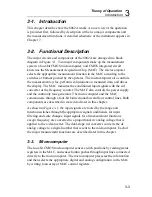
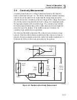
4-3. General
Information
4-4.
Handling Precautions for Using Static Sensitive
Devices
Caution
0
This instrument contains CMOS components which can
be damaged by static discharge. Static sensitive
components on the main pcb include U3 and U4. The
microcomputer pcb includes one static sensitive
component, U5, the microcomputer. To prevent damage,
take the following precautions when troubleshooting
and/or repairing the instrument:
•
Perform all work at a static-free work station.
•
Do not handle components or pcb assemblies by their connectors.
•
Wear static ground straps.
•
Use conductive foam to store components.
•
Remove all plastic, vinyl and styrofoam from the work area.
•
Use a grounded, temperature-regulated soldering iron.
4-5.
Disassembly and Reassembly
The instrument has two pcbs: the main pcb and the microcomputer pcb. To
gain access to the calibration adjustments, the backup fuse, or the LCD, you
have to remove only the top cover. You can also do some troubleshooting
with only the top cover and the top ac shield off. For other troubleshooting or
to gain access to the microcomputer pcb, you have to remove the main pcb
from the case. If you remove the main pcb from the case, you will need to
perform the calibration adjustments. Be sure to heed the notes and cautions
about special handling requirements.
Содержание 8062A
Страница 4: ......
Страница 8: ...8062A Instruction Manual iv...
Страница 10: ...8062A Instruction Manual vi...
Страница 12: ...8062A Instruction Manual viii 7 5 A1 Main PCB Schematic Diagram 7 7 7 6 A3 RMS PCB Schematic Diagram 7 8...
Страница 13: ...1 1 Chapter 1 Introduction and Specifications Contents Page 1 1 Introduction 1 3 1 2 Specifications 1 4...
Страница 14: ...8062A Instruction Manual 1 2...
Страница 24: ...8062A Instruction Manual 2 2...
Страница 50: ...8062A Instruction Manual 2 28...
Страница 52: ...8062A Instruction Manual 3 2...
Страница 62: ...8062A Instruction Manual 3 12...
Страница 64: ...8062A Instruction Manual 4 2...
Страница 90: ...8062A Instruction Manual 4 28...
Страница 92: ...8062A Instruction Manual 5 2...
Страница 97: ...List of Replaceable Parts 5 5 7 Test Button Up 1 of 2 dy37c eps Figure 5 1 8062A Final Assembly...
Страница 98: ...8062A Instruction Manual 5 8 Test Button Up 2 of 2 dy38c eps Figure 5 1 8062A Final Assembly cont...
Страница 102: ...8062A Instruction Manual 5 12 8062A 4031 iv39c eps Figure 5 2 A1 Main PCB Assembly...
Страница 106: ...8062A Instruction Manual 6 2...
Страница 108: ...8062A Instruction Manual 6 4 dy55c eps Figure 6 1 Accessories...
Страница 109: ...Accessory Information Temperature Probes 80T 150C and 80T 150F 6 6 5 dy56c eps Figure 6 1 Accessories cont...
Страница 118: ...8062A Instruction Manual 7 2...
Страница 119: ...Schematic Diagrams 7 7 3 8062A 4031 iv39c eps Figure 7 1 A1 Main PCB Component Locations TopView...
Страница 122: ...8062A Instruction Manual 7 6...
Страница 123: ...8062A Instruction Manual 7 7 8062A 1201 iu46c eps Figure 7 5 A1 Main PCB Schmatic Diagram...
Страница 124: ...8062A Instruction Manual 7 8 8060A 1003 iu61f eps Figure 7 6 A3 RMS PCB Schmatic Diagram...


