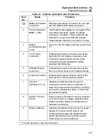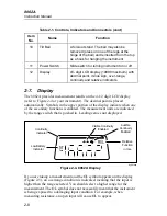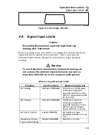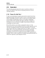
Operation Instructions
Introduction
2
2-3
2-1. Introduction
This chapter describes how to make measurements with your 8062A. Even
though you may have used a multimeter before, we suggest that you take the
time to read this material carefully so that you can take full advantage of the
wide variety of measurement functions offered by the 8062A.
2-2. Unpacking Your Instrument
Your instrument was shipped with two test leads (one red and one black), a
9V battery, and this manual. Check the shipment carefully and immediately
contact the place of purchase if anything is missing or damaged in shipment.
If reshipment is necessary, please use the original shipping container. If the
original container is not available, be sure that adequate protection is
provided to prevent damage during shipment. It is recommended that the
instrument be surrounded by at least three inches of shock-absorbing material
in the shipping container.
2-3. Battery Installation or Replacement
The 8062A is designed to operate on a single, common, inexpensive 9V
battery (NEDA 1604). You can expect a typical operating life of up to 170
hours with an alkaline battery, or 80 hours with a carbon-zinc battery. When
the battery has exhausted about 80% of its useful life the BT indicator will
appear at the far left of the display. Your instrument will continue to operate
properly for at least 24 hours with an alkaline battery after BT first appears
on the display. The 8062A also may be operated from a standard ac power
line outlet when used with the optional A81 Battery Eliminator (refer to
Chapter 7 for a description). Use the following procedure to install or replace
the battery:
Warning
To avoid electrical shock, turn off the instrument and
remove the test leads and any input signals before
replacing the battery.
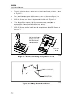
1.
Set the 8062A power switch to OFF.
2.
Remove test leads from external connections and from the 8062A input
terminals.
Содержание 8062A
Страница 4: ......
Страница 8: ...8062A Instruction Manual iv...
Страница 10: ...8062A Instruction Manual vi...
Страница 12: ...8062A Instruction Manual viii 7 5 A1 Main PCB Schematic Diagram 7 7 7 6 A3 RMS PCB Schematic Diagram 7 8...
Страница 13: ...1 1 Chapter 1 Introduction and Specifications Contents Page 1 1 Introduction 1 3 1 2 Specifications 1 4...
Страница 14: ...8062A Instruction Manual 1 2...
Страница 24: ...8062A Instruction Manual 2 2...
Страница 50: ...8062A Instruction Manual 2 28...
Страница 52: ...8062A Instruction Manual 3 2...
Страница 62: ...8062A Instruction Manual 3 12...
Страница 64: ...8062A Instruction Manual 4 2...
Страница 90: ...8062A Instruction Manual 4 28...
Страница 92: ...8062A Instruction Manual 5 2...
Страница 97: ...List of Replaceable Parts 5 5 7 Test Button Up 1 of 2 dy37c eps Figure 5 1 8062A Final Assembly...
Страница 98: ...8062A Instruction Manual 5 8 Test Button Up 2 of 2 dy38c eps Figure 5 1 8062A Final Assembly cont...
Страница 102: ...8062A Instruction Manual 5 12 8062A 4031 iv39c eps Figure 5 2 A1 Main PCB Assembly...
Страница 106: ...8062A Instruction Manual 6 2...
Страница 108: ...8062A Instruction Manual 6 4 dy55c eps Figure 6 1 Accessories...
Страница 109: ...Accessory Information Temperature Probes 80T 150C and 80T 150F 6 6 5 dy56c eps Figure 6 1 Accessories cont...
Страница 118: ...8062A Instruction Manual 7 2...
Страница 119: ...Schematic Diagrams 7 7 3 8062A 4031 iv39c eps Figure 7 1 A1 Main PCB Component Locations TopView...
Страница 122: ...8062A Instruction Manual 7 6...
Страница 123: ...8062A Instruction Manual 7 7 8062A 1201 iu46c eps Figure 7 5 A1 Main PCB Schmatic Diagram...
Страница 124: ...8062A Instruction Manual 7 8 8060A 1003 iu61f eps Figure 7 6 A3 RMS PCB Schmatic Diagram...

