


Maintenance
Troubleshooting
4
4-19
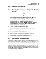
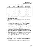
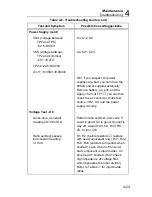
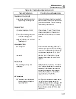
4-20. Troubleshooting
Caution
0
Static discharge can damage MOS components U3, U4,
and U5. Follow the handling precautions for static
sensitive devices previously described in this chapter.
Never remove, install or otherwise connect or disconnect
components without first setting the instrument power
switch off and disconnecting any inputs to the
instrument.
If necessary, refer to Chapter 2 for operating instructions or Chapter 3 for the
theory of operation. The troubleshooting information is supported by the
schematics and tables in Chapter 7.
4-21. Self-Tests
The 8062A offers three self-tests: power-on self-test, ratio self-test, and
switch decoding self-test. The power-on self-test is automatically performed
whenever the instrument is turned on. It is described in Chapters 2 and 3.
The other two tests function as follows:
4-22. Ratio Self-Test
The ratio self-test is an operating mode of the 8062A in which the reference
voltage for the a/d converter is applied to the a/d converter during both the
integrate and the read periods. If the instrument is functioning properly, the
display should read 10000
±
10 counts (the decimal point location depends
on the range, and does not affect the number of counts).
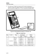
To select the ratio self-test, select a voltage or current function. Hold down
the
button while you turn on the instrument. After the power-self-test
has been completed (the display is .8.8.8.8) release the
button. The
instrument should now be in the ratio self-test mode. To cancel the ratio self-
test, press the
button or turn off the instrument.
If the count is within tolerance, it gives a strong indication that the a/d
converter is working properly. If the count deviates more than 5 counts from
10000, the probable causes are as follows ( in order of probability): a/d
converter in U3, leakage around or failure of C16, C18, Z3, R8, or the power
supply.
Содержание 8062A
Страница 4: ......
Страница 8: ...8062A Instruction Manual iv...
Страница 10: ...8062A Instruction Manual vi...
Страница 12: ...8062A Instruction Manual viii 7 5 A1 Main PCB Schematic Diagram 7 7 7 6 A3 RMS PCB Schematic Diagram 7 8...
Страница 13: ...1 1 Chapter 1 Introduction and Specifications Contents Page 1 1 Introduction 1 3 1 2 Specifications 1 4...
Страница 14: ...8062A Instruction Manual 1 2...
Страница 24: ...8062A Instruction Manual 2 2...
Страница 50: ...8062A Instruction Manual 2 28...
Страница 52: ...8062A Instruction Manual 3 2...
Страница 62: ...8062A Instruction Manual 3 12...
Страница 64: ...8062A Instruction Manual 4 2...
Страница 90: ...8062A Instruction Manual 4 28...
Страница 92: ...8062A Instruction Manual 5 2...
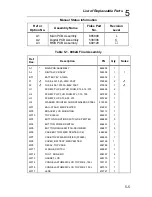
Страница 97: ...List of Replaceable Parts 5 5 7 Test Button Up 1 of 2 dy37c eps Figure 5 1 8062A Final Assembly...
Страница 98: ...8062A Instruction Manual 5 8 Test Button Up 2 of 2 dy38c eps Figure 5 1 8062A Final Assembly cont...
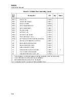
Страница 102: ...8062A Instruction Manual 5 12 8062A 4031 iv39c eps Figure 5 2 A1 Main PCB Assembly...
Страница 106: ...8062A Instruction Manual 6 2...
Страница 108: ...8062A Instruction Manual 6 4 dy55c eps Figure 6 1 Accessories...
Страница 109: ...Accessory Information Temperature Probes 80T 150C and 80T 150F 6 6 5 dy56c eps Figure 6 1 Accessories cont...
Страница 118: ...8062A Instruction Manual 7 2...
Страница 119: ...Schematic Diagrams 7 7 3 8062A 4031 iv39c eps Figure 7 1 A1 Main PCB Component Locations TopView...
Страница 122: ...8062A Instruction Manual 7 6...
Страница 123: ...8062A Instruction Manual 7 7 8062A 1201 iu46c eps Figure 7 5 A1 Main PCB Schmatic Diagram...
Страница 124: ...8062A Instruction Manual 7 8 8060A 1003 iu61f eps Figure 7 6 A3 RMS PCB Schmatic Diagram...