


8062A
Instruction Manual
2-18
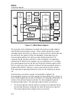
2-17. Resistance (
Ω
)
Selection of the resistance function is described in Figure 2-12. There are
four fixed ranges (200
Ω
, 2 k
Ω
, 20 k
Ω
, 200 k
Ω
) plus the autoranging M
Ω
range consisting of three ranges: 2 M
Ω
, 20 M
Ω
, and 300 M
Ω
.
In all fixed resistance ranges (200
Ω
, to 200 k
Ω
), the test voltage is less than
that required to turn on most semiconductor junctions. This feature,
sometimes referred to as “low power” ohms, aids in troubleshooting by
allowing you to measure resistors independent of effects of in-circuit
transistors and diodes. For the fixed ranges the maximum full scale voltage
across the circuit being measured is less than 250 mV. The autoranging M
Ω
ranges have enough voltage to turn on semiconductor junctions (maximum
2.5V full scale), but the current is very low (2.2
µ
A maximum).
2000mA
2000nS
A
A
COMMON
V
Ω
S
V
Ω
S
200mA
200
200k
200
µ
A
DC
AC
Hz
200mV
200
Ω
20mA
20
20k
2mA
2
2k
1000 DC
750 AC
M
Ω
REL
1000V DC
750V AC
MAX
2A MAX
500V MAX
!
!
Resistance ( )
Low (-)
High (+)
1. Select a range
2. Push switch in for
resistance function.
3. Ensure all other switches
are out (except the AC/DC
switch which can be in or out).
4. Connect the test leads as shown.
5. Ensure that the device being measured
contains no electrical energy.
6. Heed the input overload limits (Table 2-2) and
connect the test leads to the device being measured.
7. Read the measured value on the display.
dy13f.eps
Figure 2-12. Resistance Operation
Содержание 8062A
Страница 4: ......
Страница 8: ...8062A Instruction Manual iv...
Страница 10: ...8062A Instruction Manual vi...
Страница 12: ...8062A Instruction Manual viii 7 5 A1 Main PCB Schematic Diagram 7 7 7 6 A3 RMS PCB Schematic Diagram 7 8...
Страница 13: ...1 1 Chapter 1 Introduction and Specifications Contents Page 1 1 Introduction 1 3 1 2 Specifications 1 4...
Страница 14: ...8062A Instruction Manual 1 2...
Страница 24: ...8062A Instruction Manual 2 2...
Страница 50: ...8062A Instruction Manual 2 28...
Страница 52: ...8062A Instruction Manual 3 2...
Страница 62: ...8062A Instruction Manual 3 12...
Страница 64: ...8062A Instruction Manual 4 2...
Страница 90: ...8062A Instruction Manual 4 28...
Страница 92: ...8062A Instruction Manual 5 2...
Страница 97: ...List of Replaceable Parts 5 5 7 Test Button Up 1 of 2 dy37c eps Figure 5 1 8062A Final Assembly...
Страница 98: ...8062A Instruction Manual 5 8 Test Button Up 2 of 2 dy38c eps Figure 5 1 8062A Final Assembly cont...
Страница 102: ...8062A Instruction Manual 5 12 8062A 4031 iv39c eps Figure 5 2 A1 Main PCB Assembly...
Страница 106: ...8062A Instruction Manual 6 2...
Страница 108: ...8062A Instruction Manual 6 4 dy55c eps Figure 6 1 Accessories...
Страница 109: ...Accessory Information Temperature Probes 80T 150C and 80T 150F 6 6 5 dy56c eps Figure 6 1 Accessories cont...
Страница 118: ...8062A Instruction Manual 7 2...
Страница 119: ...Schematic Diagrams 7 7 3 8062A 4031 iv39c eps Figure 7 1 A1 Main PCB Component Locations TopView...
Страница 122: ...8062A Instruction Manual 7 6...
Страница 123: ...8062A Instruction Manual 7 7 8062A 1201 iu46c eps Figure 7 5 A1 Main PCB Schmatic Diagram...
Страница 124: ...8062A Instruction Manual 7 8 8060A 1003 iu61f eps Figure 7 6 A3 RMS PCB Schmatic Diagram...


