8062A
Instruction Manual
1-10
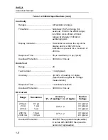
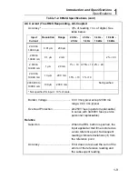
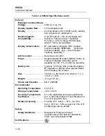
Table 1-2. 8062A Specifications (cont)
General
Maximum Common Mode
Voltage ............................... 500V dc or ac rms
Display Update Rate ......... 2.5 readings/second
Display ............................... 4½ digit duplex LCD (19,999 count), leading
zero suppression, autopolarity.
Electromagnetic
Compatibility .....................
In an RF field of 1 V/m on all ranges and
functions: Total Accuracy = Specified
Ac 2.3% of range. Performance
above 1 V/m is not specified.
Display Annunciators ....... BT (low battery indicator), REL: (relative
function enabled).
AND
R
(continuity
function enabled), and — (bar indicates
continuity detected)."""
A/D Converter.................... Dual-slope converter
Power ................................. Single standard 9V battery (NEDA 1604), or
Fluke A-81 Battery Eliminator option
available for 100, 115, or 230V ac operation.
Battery Life ........................ Typically 170 hours with an alkaline battery.
BT appears on display when approximately
20% of battery life remains.
Size..................................... 180 mm L x 86 mm W x 45 mm H (7.1” L x
3.4” W x 1.8” H)
Weight ................................ .41 kg (14.5 oz.)
Shock and Vibration ......... MIL-T-28800B
Environmental
Operating Temperature .... 0 to 50°C
Storage Temperature........ -35 to + 60°C
Accuracy Temperature
Coefficient .........................
0.1 x the applicable accuracy specification
per °C (plus the initial 23°C specification) for
0 to 18°C and 28 to 50°C.
Relative Humidity.............. 0 to 80% R.H. from 0 + 35°C, 0 to 70%
from + 35°C to + 50°C except 0 to 70% R.H.
for M
Ω
range above 20 M
Ω
.
Safety
Safety Standards............... Designed to Protection Class II
requirements of IEC 348, UL1244 ANSI
C39.5, and CSA Bulletin 556B.
Certifications..........................
Содержание 8062A
Страница 4: ......
Страница 8: ...8062A Instruction Manual iv...
Страница 10: ...8062A Instruction Manual vi...
Страница 12: ...8062A Instruction Manual viii 7 5 A1 Main PCB Schematic Diagram 7 7 7 6 A3 RMS PCB Schematic Diagram 7 8...
Страница 13: ...1 1 Chapter 1 Introduction and Specifications Contents Page 1 1 Introduction 1 3 1 2 Specifications 1 4...
Страница 14: ...8062A Instruction Manual 1 2...
Страница 24: ...8062A Instruction Manual 2 2...
Страница 50: ...8062A Instruction Manual 2 28...
Страница 52: ...8062A Instruction Manual 3 2...
Страница 62: ...8062A Instruction Manual 3 12...
Страница 64: ...8062A Instruction Manual 4 2...
Страница 90: ...8062A Instruction Manual 4 28...
Страница 92: ...8062A Instruction Manual 5 2...
Страница 97: ...List of Replaceable Parts 5 5 7 Test Button Up 1 of 2 dy37c eps Figure 5 1 8062A Final Assembly...
Страница 98: ...8062A Instruction Manual 5 8 Test Button Up 2 of 2 dy38c eps Figure 5 1 8062A Final Assembly cont...
Страница 102: ...8062A Instruction Manual 5 12 8062A 4031 iv39c eps Figure 5 2 A1 Main PCB Assembly...
Страница 106: ...8062A Instruction Manual 6 2...
Страница 108: ...8062A Instruction Manual 6 4 dy55c eps Figure 6 1 Accessories...
Страница 109: ...Accessory Information Temperature Probes 80T 150C and 80T 150F 6 6 5 dy56c eps Figure 6 1 Accessories cont...
Страница 118: ...8062A Instruction Manual 7 2...
Страница 119: ...Schematic Diagrams 7 7 3 8062A 4031 iv39c eps Figure 7 1 A1 Main PCB Component Locations TopView...
Страница 122: ...8062A Instruction Manual 7 6...
Страница 123: ...8062A Instruction Manual 7 7 8062A 1201 iu46c eps Figure 7 5 A1 Main PCB Schmatic Diagram...
Страница 124: ...8062A Instruction Manual 7 8 8060A 1003 iu61f eps Figure 7 6 A3 RMS PCB Schmatic Diagram...

