8062A
Instruction Manual
4-24
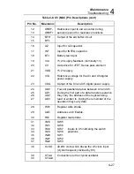
Table 4-6. Troubleshooting Guide (cont)
Test and Symptom
Possible Cause/Suggestions
Voltage Test - DC (cont)
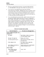
High impedance dc readings
0.00, normal dc
readings correct
R1
DC readings incorrect for
all ranges
Leakage from pcb, U3-6/7,
contamination
DC readings correct for
200 mV, 2V
incorrect
for 20V, 200V, 1000V
Input divider or input divider switches,
R2
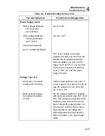
Voltage Test - AC
DC reading correct,
ac readings incorrect
Switches S3D, S3B
Check power supply connections
J13
Vss
J7
Com
J12
Vdd
Resistance Test
All ranges incorrect
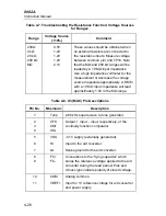
Ohms source voltage inadequate -
using a voltmeter in the 2V or 20V
range, measure ohms source voltage
between TP11 and common. Refer to
Table 4-7 for correct values.
Q3, Q4, RT1, R2, R1, Z5
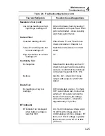
All ranges incorrect
CR1 not supplying enough current
(particularly if 200
Ω
range noisy).
Select diode test, connect an external
1 k
Ω
resistor across the inputs and
measure the voltage drop across the
resistor - should be approximately 1V
(
±
10%).
CR1 supplying proper current,
but reading off
Check values of the reference
resistors for the range not working.
Check voltage drops across the
known and unknown resistors and
make sure the ratio works properly.
Содержание 8062A
Страница 4: ......
Страница 8: ...8062A Instruction Manual iv...
Страница 10: ...8062A Instruction Manual vi...
Страница 12: ...8062A Instruction Manual viii 7 5 A1 Main PCB Schematic Diagram 7 7 7 6 A3 RMS PCB Schematic Diagram 7 8...
Страница 13: ...1 1 Chapter 1 Introduction and Specifications Contents Page 1 1 Introduction 1 3 1 2 Specifications 1 4...
Страница 14: ...8062A Instruction Manual 1 2...
Страница 24: ...8062A Instruction Manual 2 2...
Страница 50: ...8062A Instruction Manual 2 28...
Страница 52: ...8062A Instruction Manual 3 2...
Страница 62: ...8062A Instruction Manual 3 12...
Страница 64: ...8062A Instruction Manual 4 2...
Страница 90: ...8062A Instruction Manual 4 28...
Страница 92: ...8062A Instruction Manual 5 2...
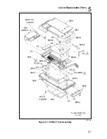
Страница 97: ...List of Replaceable Parts 5 5 7 Test Button Up 1 of 2 dy37c eps Figure 5 1 8062A Final Assembly...
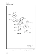
Страница 98: ...8062A Instruction Manual 5 8 Test Button Up 2 of 2 dy38c eps Figure 5 1 8062A Final Assembly cont...
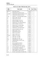
Страница 102: ...8062A Instruction Manual 5 12 8062A 4031 iv39c eps Figure 5 2 A1 Main PCB Assembly...
Страница 106: ...8062A Instruction Manual 6 2...
Страница 108: ...8062A Instruction Manual 6 4 dy55c eps Figure 6 1 Accessories...
Страница 109: ...Accessory Information Temperature Probes 80T 150C and 80T 150F 6 6 5 dy56c eps Figure 6 1 Accessories cont...
Страница 118: ...8062A Instruction Manual 7 2...
Страница 119: ...Schematic Diagrams 7 7 3 8062A 4031 iv39c eps Figure 7 1 A1 Main PCB Component Locations TopView...
Страница 122: ...8062A Instruction Manual 7 6...
Страница 123: ...8062A Instruction Manual 7 7 8062A 1201 iu46c eps Figure 7 5 A1 Main PCB Schmatic Diagram...
Страница 124: ...8062A Instruction Manual 7 8 8060A 1003 iu61f eps Figure 7 6 A3 RMS PCB Schmatic Diagram...

