


8062A
Instruction Manual
2-10
2-9. Operation
The following paragraphs describe the power-on self-test, and how to
operate your 8062A in each of the seven primary functions or the two
secondary functions.
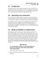
2-10. Power-On Self-Test
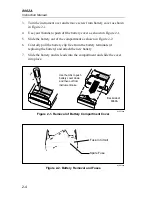
To turn on your instrument, locate the green switch on the left side of the
instrument and slide it forward. Whenever you turn on the instrument, the
8062A automatically performs a self-test to make sure the display and the
microcomputer are functioning properly. If everything is functioning
properly, all the LCD segments in the display will turn on (Figure 2-4).
After about one or two seconds, the display will go blank briefly before
responding to switch selections.
If the LCD segments do not all turn on during the self-test, or if the
instrument does not clear the display after the test and then respond to switch
selections, something is probably wrong with the instrument. Try the test
again, and if it fails, have a qualified person refer to Chapter 4. If there is no
display when you turn on the instrument, check the battery and battery
connections. You will find that if you turn off your instrument and then
immediately turn it back on, a random assortment of LCD segments may be
displayed. This is normal. After about a second the instrument should turn on
all the LCD segments as usual during the self-test.
Содержание 8062A
Страница 4: ......
Страница 8: ...8062A Instruction Manual iv...
Страница 10: ...8062A Instruction Manual vi...
Страница 12: ...8062A Instruction Manual viii 7 5 A1 Main PCB Schematic Diagram 7 7 7 6 A3 RMS PCB Schematic Diagram 7 8...
Страница 13: ...1 1 Chapter 1 Introduction and Specifications Contents Page 1 1 Introduction 1 3 1 2 Specifications 1 4...
Страница 14: ...8062A Instruction Manual 1 2...
Страница 24: ...8062A Instruction Manual 2 2...
Страница 50: ...8062A Instruction Manual 2 28...
Страница 52: ...8062A Instruction Manual 3 2...
Страница 62: ...8062A Instruction Manual 3 12...
Страница 64: ...8062A Instruction Manual 4 2...
Страница 90: ...8062A Instruction Manual 4 28...
Страница 92: ...8062A Instruction Manual 5 2...
Страница 97: ...List of Replaceable Parts 5 5 7 Test Button Up 1 of 2 dy37c eps Figure 5 1 8062A Final Assembly...
Страница 98: ...8062A Instruction Manual 5 8 Test Button Up 2 of 2 dy38c eps Figure 5 1 8062A Final Assembly cont...
Страница 102: ...8062A Instruction Manual 5 12 8062A 4031 iv39c eps Figure 5 2 A1 Main PCB Assembly...
Страница 106: ...8062A Instruction Manual 6 2...
Страница 108: ...8062A Instruction Manual 6 4 dy55c eps Figure 6 1 Accessories...
Страница 109: ...Accessory Information Temperature Probes 80T 150C and 80T 150F 6 6 5 dy56c eps Figure 6 1 Accessories cont...
Страница 118: ...8062A Instruction Manual 7 2...
Страница 119: ...Schematic Diagrams 7 7 3 8062A 4031 iv39c eps Figure 7 1 A1 Main PCB Component Locations TopView...
Страница 122: ...8062A Instruction Manual 7 6...
Страница 123: ...8062A Instruction Manual 7 7 8062A 1201 iu46c eps Figure 7 5 A1 Main PCB Schmatic Diagram...
Страница 124: ...8062A Instruction Manual 7 8 8060A 1003 iu61f eps Figure 7 6 A3 RMS PCB Schmatic Diagram...


