


Operation Instructions
Operation
2
2-11
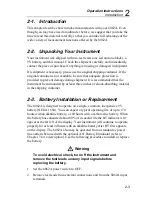
2-11. AC/DC Voltage (V)
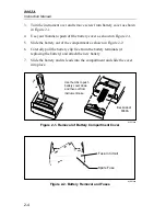
Selection of the ac or dc voltage (V) functions is described in Figure 2-6.
The 8062A offers five ac and five dc voltage ranges: 200 mV, 2V, 20V,
200V, and 750V ac/1000V dc. All ranges present a 10 M
Ω
input impedance,
which is shunted by <100 pF.
2000mA
A
A
COMMON
V
Ω
S
V
Ω
S
200mA
200
200k
200
µ
A
DC
AC
200mV
200
Ω
20mA
20
20k
2mA
2
2k
1000 DC
750 AC
M
Ω
REL
1000V DC
750V AC
MAX
2A MAX
500V MAX
!
!
Low (-)
Voltage (V)
High (+)
1. Select a range.
2. Set AC/DC switch out
for DC, in for AC.
3. Press switch in to select
voltage function.
4. Ensure all other switches are out.
5. Connect the test leads as shown above.
6. Heed the input overload limits (Table 2-2) and connect the leads
to the circuit being measured.
7. Read the measured value on the display.
dy08f.eps
Figure 2-6. Voltage Operation
2-12. True RMS Measurement
One of the most useful features of the 8062A is the direct measurement of
true rms or effective ac voltages and ac currents. Mathematically, rms is
defined as the square root of the sum of the squares of the ac and dc
components. In physical terms, rms is equivalent to the dc value that
dissipates the same amount of heat in a resistor as the original waveform.
The reason that rms is so valuable is that it greatly simplifies the analysis of
Содержание 8062A
Страница 4: ......
Страница 8: ...8062A Instruction Manual iv...
Страница 10: ...8062A Instruction Manual vi...
Страница 12: ...8062A Instruction Manual viii 7 5 A1 Main PCB Schematic Diagram 7 7 7 6 A3 RMS PCB Schematic Diagram 7 8...
Страница 13: ...1 1 Chapter 1 Introduction and Specifications Contents Page 1 1 Introduction 1 3 1 2 Specifications 1 4...
Страница 14: ...8062A Instruction Manual 1 2...
Страница 24: ...8062A Instruction Manual 2 2...
Страница 50: ...8062A Instruction Manual 2 28...
Страница 52: ...8062A Instruction Manual 3 2...
Страница 62: ...8062A Instruction Manual 3 12...
Страница 64: ...8062A Instruction Manual 4 2...
Страница 90: ...8062A Instruction Manual 4 28...
Страница 92: ...8062A Instruction Manual 5 2...
Страница 97: ...List of Replaceable Parts 5 5 7 Test Button Up 1 of 2 dy37c eps Figure 5 1 8062A Final Assembly...
Страница 98: ...8062A Instruction Manual 5 8 Test Button Up 2 of 2 dy38c eps Figure 5 1 8062A Final Assembly cont...
Страница 102: ...8062A Instruction Manual 5 12 8062A 4031 iv39c eps Figure 5 2 A1 Main PCB Assembly...
Страница 106: ...8062A Instruction Manual 6 2...
Страница 108: ...8062A Instruction Manual 6 4 dy55c eps Figure 6 1 Accessories...
Страница 109: ...Accessory Information Temperature Probes 80T 150C and 80T 150F 6 6 5 dy56c eps Figure 6 1 Accessories cont...
Страница 118: ...8062A Instruction Manual 7 2...
Страница 119: ...Schematic Diagrams 7 7 3 8062A 4031 iv39c eps Figure 7 1 A1 Main PCB Component Locations TopView...
Страница 122: ...8062A Instruction Manual 7 6...
Страница 123: ...8062A Instruction Manual 7 7 8062A 1201 iu46c eps Figure 7 5 A1 Main PCB Schmatic Diagram...
Страница 124: ...8062A Instruction Manual 7 8 8060A 1003 iu61f eps Figure 7 6 A3 RMS PCB Schmatic Diagram...