


Operation Instructions
Operation
2
2-13
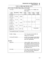
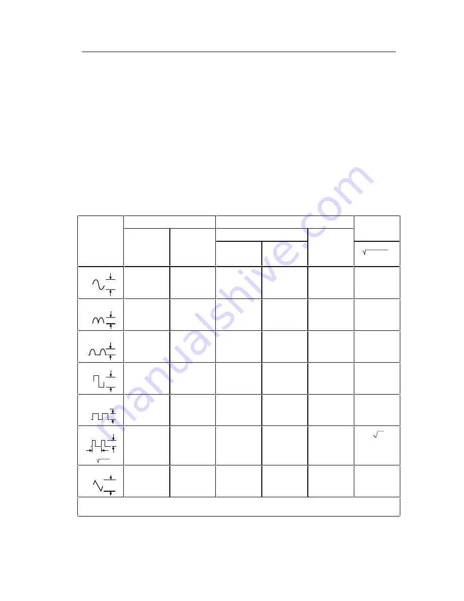
2-14. Waveform Comparison and Conversion
Figure 2-8 shows the relationship between common waveforms and the
display readings for the 8062A and average-responding meters. Figure 2-8
also illustrates the relationship between ac and dc measurements for ac-
coupled meters. For example, consider the first waveform, a 1.414V (0-pk)
sinewave. Both the 8062A and the rms-calibrated average-responding meter
display the correct rms reading of 1.000V (the dc component equals 0).
However, consider the 1.414V (0-pk) rectified square wave. Both types of
meters correctly measure the dc component (0.707V). But only the 8062A
correctly measures the ac component (0.707V). The average-responding
meter measures 0.785V, which amounts to a 5.6% error in the total rms
measurement calculated from the ac and dc components.
AC Coupled
Peak Voltages
Display Readings
DC and AC
Input
AC Component Only
DC
Total RMS
Waveform
PK - PK
0 - PK
RMS CAL*
8062A
Component
only
TRUE RMS =
ac + dc
2
2
Sine
PK
0
PK-PK
2.828
1.414
1.000
1.000
0.000
1.000
PK-PK
0
PK
Rectified Sine
(Full Wave)
1.414
1.414
0.421
0.435
0.900
1.000
PK-PK
Rectified Sine
(Half Wave)
0
PK
2.000
2.000
0.764
0.771
0.636
1.000
PK-PK
0
PK
Square
2.000
1.000
1.110
1.000
0.000
1.000
PK-PK
0
PK
Rectified
Square
1.414
1.414
0.785
0.707
0.707
1.000
PK-PK
Rectangular
Pulse
0
PK
X
Y
D = X/Y
K = D-D
2
2.000
2.000
2.22K
2K
2D
2
D
PK-PK
Triangle
Sawtooth
0
PK
3.464
1.732
0.960
1.000
0.000
1.000
RMS CAL is the displayed value for average responding meters that are calibrated to display RMS for sine waves.
Figure 2-8. Multiplication Factors for Converting Waveforms
Содержание 8062A
Страница 4: ......
Страница 8: ...8062A Instruction Manual iv...
Страница 10: ...8062A Instruction Manual vi...
Страница 12: ...8062A Instruction Manual viii 7 5 A1 Main PCB Schematic Diagram 7 7 7 6 A3 RMS PCB Schematic Diagram 7 8...
Страница 13: ...1 1 Chapter 1 Introduction and Specifications Contents Page 1 1 Introduction 1 3 1 2 Specifications 1 4...
Страница 14: ...8062A Instruction Manual 1 2...
Страница 24: ...8062A Instruction Manual 2 2...
Страница 50: ...8062A Instruction Manual 2 28...
Страница 52: ...8062A Instruction Manual 3 2...
Страница 62: ...8062A Instruction Manual 3 12...
Страница 64: ...8062A Instruction Manual 4 2...
Страница 90: ...8062A Instruction Manual 4 28...
Страница 92: ...8062A Instruction Manual 5 2...
Страница 97: ...List of Replaceable Parts 5 5 7 Test Button Up 1 of 2 dy37c eps Figure 5 1 8062A Final Assembly...
Страница 98: ...8062A Instruction Manual 5 8 Test Button Up 2 of 2 dy38c eps Figure 5 1 8062A Final Assembly cont...
Страница 102: ...8062A Instruction Manual 5 12 8062A 4031 iv39c eps Figure 5 2 A1 Main PCB Assembly...
Страница 106: ...8062A Instruction Manual 6 2...
Страница 108: ...8062A Instruction Manual 6 4 dy55c eps Figure 6 1 Accessories...
Страница 109: ...Accessory Information Temperature Probes 80T 150C and 80T 150F 6 6 5 dy56c eps Figure 6 1 Accessories cont...
Страница 118: ...8062A Instruction Manual 7 2...
Страница 119: ...Schematic Diagrams 7 7 3 8062A 4031 iv39c eps Figure 7 1 A1 Main PCB Component Locations TopView...
Страница 122: ...8062A Instruction Manual 7 6...
Страница 123: ...8062A Instruction Manual 7 7 8062A 1201 iu46c eps Figure 7 5 A1 Main PCB Schmatic Diagram...
Страница 124: ...8062A Instruction Manual 7 8 8060A 1003 iu61f eps Figure 7 6 A3 RMS PCB Schmatic Diagram...


