4-1
Chapter 4
Maintenance
Contents
Page
4-1. Introduction .................................................................... 4-3
4-2. Service Information ........................................................ 4-3
4-3. General Information ....................................................... 4-5
4-4.
Handling Precautions for Using Static Sensitive
Devices ...................................................................... 4-5
4-5.
Disassembly and Reassembly ..................................... 4-5
4-6.
Calibration and Backup Fuse Access ...................... 4-6
4-7.
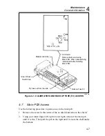
Main PCB Access.................................................... 4-7
4-8.
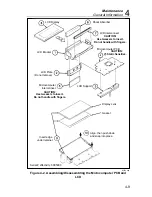
LCD and Microcomputer PCB Disassembly and
Assembly................................................................. 4-8
4-9.
Backup Fuse Replacement .......................................... 4-11
4-10.
Cleaning ...................................................................... 4-11
4-11. Performance Tests .......................................................... 4-12
4-12.
Initial Procedure.......................................................... 4-12
4-13.
Microcomputer and Display Test................................ 4-12
4-14.
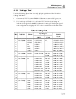
Voltage Test................................................................ 4-13
4-15.
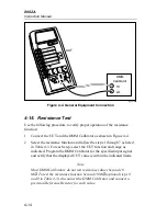
Resistance Test ........................................................... 4-14
4-16.
Continuity Test............................................................ 4-15
4-17.
Current Test ................................................................ 4-15
4-18.
Diode Test................................................................... 4-17
4-19. Calibration Adjustments ................................................. 4-17
4-20. Troubleshooting.............................................................. 4-19
4-21.
Self-Tests .................................................................... 4-19
4-22.
Ratio Self-Test......................................................... 4-19
4-23.
Switch Decoding Self-Test...................................... 4-20
4-24.
Troubleshooting Guide ............................................... 4-21
Содержание 8062A
Страница 4: ......
Страница 8: ...8062A Instruction Manual iv...
Страница 10: ...8062A Instruction Manual vi...
Страница 12: ...8062A Instruction Manual viii 7 5 A1 Main PCB Schematic Diagram 7 7 7 6 A3 RMS PCB Schematic Diagram 7 8...
Страница 13: ...1 1 Chapter 1 Introduction and Specifications Contents Page 1 1 Introduction 1 3 1 2 Specifications 1 4...
Страница 14: ...8062A Instruction Manual 1 2...
Страница 24: ...8062A Instruction Manual 2 2...
Страница 50: ...8062A Instruction Manual 2 28...
Страница 52: ...8062A Instruction Manual 3 2...
Страница 62: ...8062A Instruction Manual 3 12...
Страница 64: ...8062A Instruction Manual 4 2...
Страница 90: ...8062A Instruction Manual 4 28...
Страница 92: ...8062A Instruction Manual 5 2...
Страница 97: ...List of Replaceable Parts 5 5 7 Test Button Up 1 of 2 dy37c eps Figure 5 1 8062A Final Assembly...
Страница 98: ...8062A Instruction Manual 5 8 Test Button Up 2 of 2 dy38c eps Figure 5 1 8062A Final Assembly cont...
Страница 102: ...8062A Instruction Manual 5 12 8062A 4031 iv39c eps Figure 5 2 A1 Main PCB Assembly...
Страница 106: ...8062A Instruction Manual 6 2...
Страница 108: ...8062A Instruction Manual 6 4 dy55c eps Figure 6 1 Accessories...
Страница 109: ...Accessory Information Temperature Probes 80T 150C and 80T 150F 6 6 5 dy56c eps Figure 6 1 Accessories cont...
Страница 118: ...8062A Instruction Manual 7 2...
Страница 119: ...Schematic Diagrams 7 7 3 8062A 4031 iv39c eps Figure 7 1 A1 Main PCB Component Locations TopView...
Страница 122: ...8062A Instruction Manual 7 6...
Страница 123: ...8062A Instruction Manual 7 7 8062A 1201 iu46c eps Figure 7 5 A1 Main PCB Schmatic Diagram...
Страница 124: ...8062A Instruction Manual 7 8 8060A 1003 iu61f eps Figure 7 6 A3 RMS PCB Schmatic Diagram...

