


Maintenance
Performance Tests
4
4-13
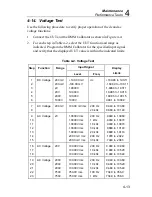
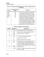
4-14. Voltage Test
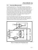
Use the following procedure to verify proper operation of the dc and ac
voltage functions.
1.
Connect the UUT and the DMM Calibrator as shown in Figure 4-4.
2.
For each step in Table 4-2, select the UUT function and range as
indicated. Program the DMM Calibrator for the specified input signal
and verify that the displayed UUT value is within the indicated limits.
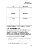
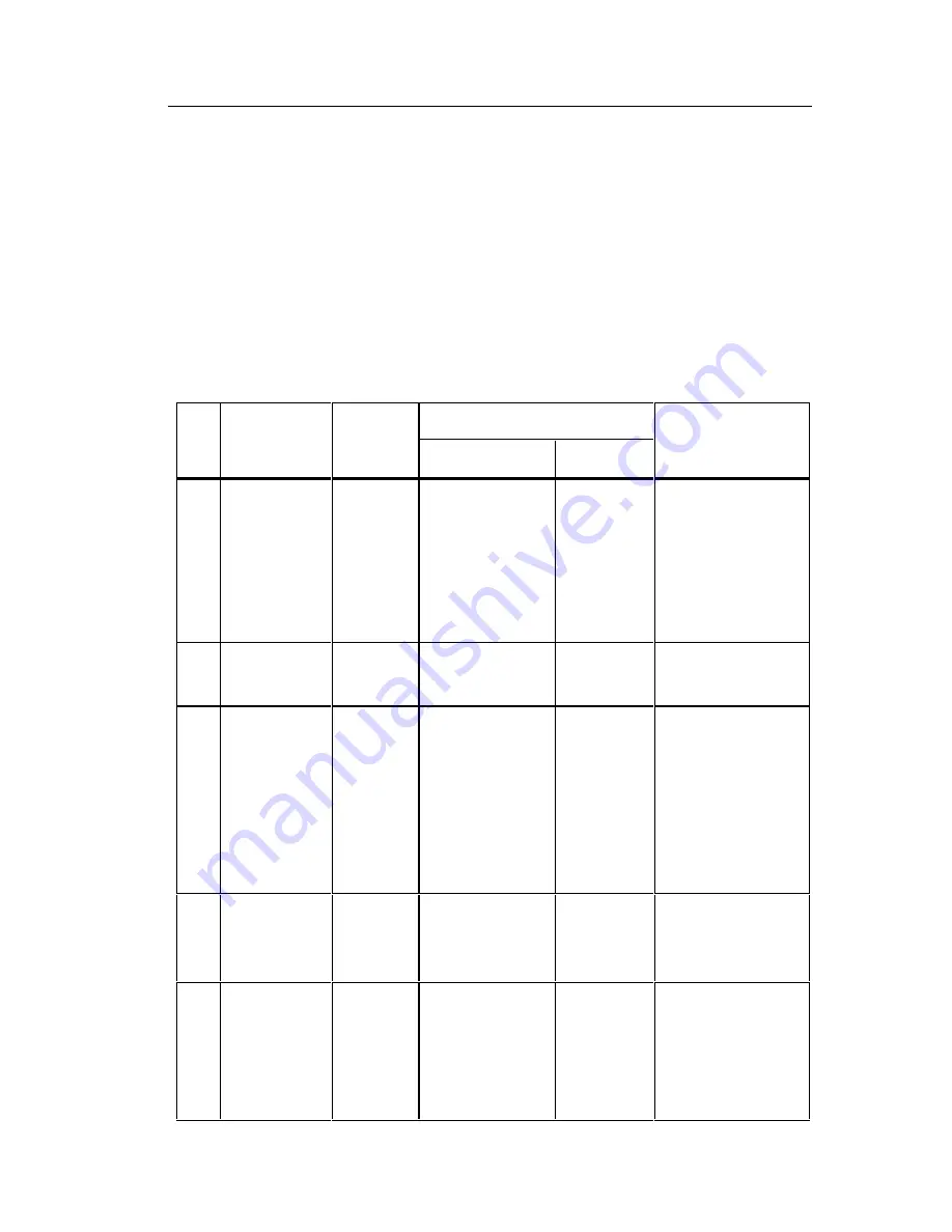
Table 4-2. Voltage Test
Step
Function
Range
Input Signal
Display
Level
Freq.
Limits
1
2
3
4
5
6
DC Voltage
200 mV
200 mV
2V
20V
200V
1000V
+ 190.00 mV
-190.00 mV
1.9000V
19.000V
190.00V
1000V
dc
+189.90 to 190.11
-189.89 to -190.11
1.8989 to 1.9011
18.985 to 19.015
189.85 to 190.15
999.1 to 1000.9
7
8
AC Voltage
200 mV
100.00 mV rms
200 Hz
20 kHz
99.40 to 100.60
98.60 to 101.40
9
10
11
12
13
14
15
AC Voltage
2V
1.0000V rms
1.0000V rms
1.0000V rms
1.0000V rms
1.0000V rms
200.0 mV rms
200.0 mV rms
200 Hz
1 kHz
10 kHz
30 kHz
20 kHz
200 Hz
30 kHz
.9940 to 1.0060
.9930 to 1.0070
.9930 to 1.0070
.9860 to 1.0140
.9890 to 1.0110
.1978 to .2022
.7940 to .2060
16
17
18
AC Voltage
20V
10.000V rms
10.000V rms
10.000V rms
200 Hz
10 kHz
30 kHz
9.940 to 10.060
9.480 to 10.520
9.460 to 10.540
19
20
21
22
23
AC Voltage
200V
200V
200V
750V
750V
100.00V rms
100.00V rms
100.00V rms
750.0V rms
750.0V rms
200 Hz
10 kHz
30 kHz
100 Hz
1 kHz
99.40 to 100.60
94.80 to 105.20
94.60 to 105.40
734.0 to 766.0
734.0 to 766.0
Содержание 8062A
Страница 4: ......
Страница 8: ...8062A Instruction Manual iv...
Страница 10: ...8062A Instruction Manual vi...
Страница 12: ...8062A Instruction Manual viii 7 5 A1 Main PCB Schematic Diagram 7 7 7 6 A3 RMS PCB Schematic Diagram 7 8...
Страница 13: ...1 1 Chapter 1 Introduction and Specifications Contents Page 1 1 Introduction 1 3 1 2 Specifications 1 4...
Страница 14: ...8062A Instruction Manual 1 2...
Страница 24: ...8062A Instruction Manual 2 2...
Страница 50: ...8062A Instruction Manual 2 28...
Страница 52: ...8062A Instruction Manual 3 2...
Страница 62: ...8062A Instruction Manual 3 12...
Страница 64: ...8062A Instruction Manual 4 2...
Страница 90: ...8062A Instruction Manual 4 28...
Страница 92: ...8062A Instruction Manual 5 2...
Страница 97: ...List of Replaceable Parts 5 5 7 Test Button Up 1 of 2 dy37c eps Figure 5 1 8062A Final Assembly...
Страница 98: ...8062A Instruction Manual 5 8 Test Button Up 2 of 2 dy38c eps Figure 5 1 8062A Final Assembly cont...
Страница 102: ...8062A Instruction Manual 5 12 8062A 4031 iv39c eps Figure 5 2 A1 Main PCB Assembly...
Страница 106: ...8062A Instruction Manual 6 2...
Страница 108: ...8062A Instruction Manual 6 4 dy55c eps Figure 6 1 Accessories...
Страница 109: ...Accessory Information Temperature Probes 80T 150C and 80T 150F 6 6 5 dy56c eps Figure 6 1 Accessories cont...
Страница 118: ...8062A Instruction Manual 7 2...
Страница 119: ...Schematic Diagrams 7 7 3 8062A 4031 iv39c eps Figure 7 1 A1 Main PCB Component Locations TopView...
Страница 122: ...8062A Instruction Manual 7 6...
Страница 123: ...8062A Instruction Manual 7 7 8062A 1201 iu46c eps Figure 7 5 A1 Main PCB Schmatic Diagram...
Страница 124: ...8062A Instruction Manual 7 8 8060A 1003 iu61f eps Figure 7 6 A3 RMS PCB Schmatic Diagram...


