8062A
Instruction Manual
1-6
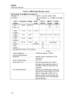
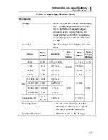
Table 1-2. 8062A Specifications (cont)
AC Voltage (True RMS, AC-Coupled)
Ranges .............................................. 200 mV, 2V, 20V, 200V, 750V
Accuracy *..........................................
±
(% of r no. of digits). See table
below:
Input
Voltage
Resolution
Range
20 Hz -
45 Hz
45 Hz -
500 Hz
500 Hz -
10 kHz
10 kHz -
30 kHz
20.0 -
199.99 mV
.01 mV
200 mV
0.5%
+ 20
1%
+ 40
.2000 -
1.9999V
.1 mV
2V
1% +10
2.000 -
19.999V
1 mV
20V
0.5% +12
5% +20
5% +40
20.00 -
199.99V
10 mV
200V
75.0 -
499.9V
100 mV
750V
Not
Specified
1%
+10
Not Specified
500.0 -
750.0V
2%
+10
* Not specified for input < 10% of range.
1 kHz
Input Impedance ......................... 10 M
Ω
shunted by <100 pF
Common Mode Noise
Rejection ..................................... >60 dB at 50 Hz and 60 Hz (1 k
Ω
imbalance)
Crest Factor Range..................... 1:1 to 3:1
Response Time........................... Five seconds maximum to rated
accuracy within selected range, 12
seconds to rated accuracy from an
overload.
Overload Protection .................... 750V rms or 1000V peak continuous
except 20 seconds maximum on the
200 mV range above 300V rms or
300V dc. Input not to exceed a volt-
hertz product of 1x10
7
(for example,
200V at 50 kHz).
Содержание 8062A
Страница 4: ......
Страница 8: ...8062A Instruction Manual iv...
Страница 10: ...8062A Instruction Manual vi...
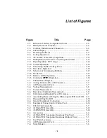
Страница 12: ...8062A Instruction Manual viii 7 5 A1 Main PCB Schematic Diagram 7 7 7 6 A3 RMS PCB Schematic Diagram 7 8...
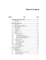
Страница 13: ...1 1 Chapter 1 Introduction and Specifications Contents Page 1 1 Introduction 1 3 1 2 Specifications 1 4...
Страница 14: ...8062A Instruction Manual 1 2...
Страница 24: ...8062A Instruction Manual 2 2...
Страница 50: ...8062A Instruction Manual 2 28...
Страница 52: ...8062A Instruction Manual 3 2...
Страница 62: ...8062A Instruction Manual 3 12...
Страница 64: ...8062A Instruction Manual 4 2...
Страница 90: ...8062A Instruction Manual 4 28...
Страница 92: ...8062A Instruction Manual 5 2...
Страница 97: ...List of Replaceable Parts 5 5 7 Test Button Up 1 of 2 dy37c eps Figure 5 1 8062A Final Assembly...
Страница 98: ...8062A Instruction Manual 5 8 Test Button Up 2 of 2 dy38c eps Figure 5 1 8062A Final Assembly cont...
Страница 102: ...8062A Instruction Manual 5 12 8062A 4031 iv39c eps Figure 5 2 A1 Main PCB Assembly...
Страница 106: ...8062A Instruction Manual 6 2...
Страница 108: ...8062A Instruction Manual 6 4 dy55c eps Figure 6 1 Accessories...
Страница 109: ...Accessory Information Temperature Probes 80T 150C and 80T 150F 6 6 5 dy56c eps Figure 6 1 Accessories cont...
Страница 118: ...8062A Instruction Manual 7 2...
Страница 119: ...Schematic Diagrams 7 7 3 8062A 4031 iv39c eps Figure 7 1 A1 Main PCB Component Locations TopView...
Страница 122: ...8062A Instruction Manual 7 6...
Страница 123: ...8062A Instruction Manual 7 7 8062A 1201 iu46c eps Figure 7 5 A1 Main PCB Schmatic Diagram...
Страница 124: ...8062A Instruction Manual 7 8 8060A 1003 iu61f eps Figure 7 6 A3 RMS PCB Schmatic Diagram...


