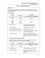

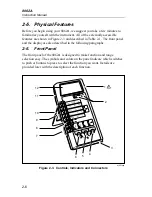


Operation Instructions
Signal Input Limits
2
2-9
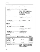
dy07f.eps
Figure 2-5. Overrange Indicator
2-8. Signal Input Limits
Caution
Exceeding the maximum input overload limits can
damage your instrument.
Before you begin to use your 8062A, it is important to note the maximum
inputs that may be applied to the instrument. Table 2-2 presents the
maximum inputs that are allowed for each function, range, and input
terminal.
Warning
To avoid electrical shock and/or instrument damage, do
not connect the common input terminal to any source
more than 500 volts dc or rms ac above earth ground.
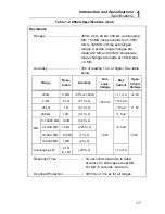
Table 2-2. Input Overload Limits
Function
Input Terminals
Maximum Input Limit
AC Voltage
V
Ω
S and COMMON
750V rms or 1000V peak
continuous except 20
seconds maximum on the
200 mV range above 300V
dc or ac rms.
DC Voltage
V
Ω
S and COMMON
1000V dc or peak ac
continuous except 20
seconds maximum on the
200 mV and 2V ranges
above 300V dc or ac rms.
AC or DC Current
A and COMMON
2A maximum, fuse
protected to 600V dc or ac
rms.
Resistance, Diode
Test, and Continuity
V
Ω
and COMMON
300V dc or ac rms.
Содержание 8062A
Страница 4: ......
Страница 8: ...8062A Instruction Manual iv...
Страница 10: ...8062A Instruction Manual vi...
Страница 12: ...8062A Instruction Manual viii 7 5 A1 Main PCB Schematic Diagram 7 7 7 6 A3 RMS PCB Schematic Diagram 7 8...
Страница 13: ...1 1 Chapter 1 Introduction and Specifications Contents Page 1 1 Introduction 1 3 1 2 Specifications 1 4...
Страница 14: ...8062A Instruction Manual 1 2...
Страница 24: ...8062A Instruction Manual 2 2...
Страница 50: ...8062A Instruction Manual 2 28...
Страница 52: ...8062A Instruction Manual 3 2...
Страница 62: ...8062A Instruction Manual 3 12...
Страница 64: ...8062A Instruction Manual 4 2...
Страница 90: ...8062A Instruction Manual 4 28...
Страница 92: ...8062A Instruction Manual 5 2...
Страница 97: ...List of Replaceable Parts 5 5 7 Test Button Up 1 of 2 dy37c eps Figure 5 1 8062A Final Assembly...
Страница 98: ...8062A Instruction Manual 5 8 Test Button Up 2 of 2 dy38c eps Figure 5 1 8062A Final Assembly cont...
Страница 102: ...8062A Instruction Manual 5 12 8062A 4031 iv39c eps Figure 5 2 A1 Main PCB Assembly...
Страница 106: ...8062A Instruction Manual 6 2...
Страница 108: ...8062A Instruction Manual 6 4 dy55c eps Figure 6 1 Accessories...
Страница 109: ...Accessory Information Temperature Probes 80T 150C and 80T 150F 6 6 5 dy56c eps Figure 6 1 Accessories cont...
Страница 118: ...8062A Instruction Manual 7 2...
Страница 119: ...Schematic Diagrams 7 7 3 8062A 4031 iv39c eps Figure 7 1 A1 Main PCB Component Locations TopView...
Страница 122: ...8062A Instruction Manual 7 6...
Страница 123: ...8062A Instruction Manual 7 7 8062A 1201 iu46c eps Figure 7 5 A1 Main PCB Schmatic Diagram...
Страница 124: ...8062A Instruction Manual 7 8 8060A 1003 iu61f eps Figure 7 6 A3 RMS PCB Schmatic Diagram...


