


8062A
Instruction Manual
6-6
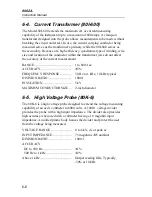
6-4. Current Transformer (80I-600)
The Model 80I-600 extends the maximum 2A ac current measuring
capability of the instrument up to a maximum of 600 amps. A clamp-on
transformer designed into the probe allows measurements to be made without
breaking the circuit under test. In use, the current carrying conductor being
measured serves as the transformer’s primary, while the 80I-600 serves as
the secondary. Because of a high efficiency, quadrature type of winding, wire
size and location of the conductor within the transformer jaws do not affect
the accuracy of the current measurement.
RANGE .............................................
1 to 600A ac
ACCURACY.....................................
±
3%
FREQUENCY RESPONSE ..............
30 Hz to 1 kHz, 10 kHz typical
DIVISION RATIO............................
1000:1
INSULATION...................................
5 kV
MAXIMUM CONDUCTOR SIZE ...
2-inch diameter
6-5. High Voltage Probe (80K-6)
The 80K-6 is a high voltage probe designed to extend the voltage measuring
capability of an ac dc voltmeter to 6000 volts. A 1000:1 voltage divider
provides the probe with a high input impedance. The divider also provides
high accuracy when used with a voltmeter having a 10 megohm input
impedance. A molded plastic body houses the divider and protect the user
from the voltage being measured.
VOLTAGE RANGE .........................
0 to 6 kV, dc or peak ac
INPUT IMPEDANCE.......................
75 megohms
±
25 nominal
DIVISION RATIO............................
1000:1
ACCURACY
DC to 500 Hz ..................................
500 Hz to 1 kHz ..............................
±
1%
±
2%
Above 1 kHz .....................................
Output reading falls. Typically,
-30% at 10 kHz
Содержание 8062A
Страница 4: ......
Страница 8: ...8062A Instruction Manual iv...
Страница 10: ...8062A Instruction Manual vi...
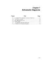
Страница 12: ...8062A Instruction Manual viii 7 5 A1 Main PCB Schematic Diagram 7 7 7 6 A3 RMS PCB Schematic Diagram 7 8...
Страница 13: ...1 1 Chapter 1 Introduction and Specifications Contents Page 1 1 Introduction 1 3 1 2 Specifications 1 4...
Страница 14: ...8062A Instruction Manual 1 2...
Страница 24: ...8062A Instruction Manual 2 2...
Страница 50: ...8062A Instruction Manual 2 28...
Страница 52: ...8062A Instruction Manual 3 2...
Страница 62: ...8062A Instruction Manual 3 12...
Страница 64: ...8062A Instruction Manual 4 2...
Страница 90: ...8062A Instruction Manual 4 28...
Страница 92: ...8062A Instruction Manual 5 2...
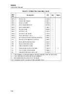
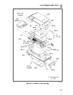
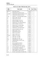
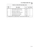
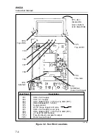
Страница 97: ...List of Replaceable Parts 5 5 7 Test Button Up 1 of 2 dy37c eps Figure 5 1 8062A Final Assembly...
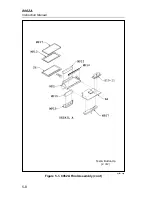
Страница 98: ...8062A Instruction Manual 5 8 Test Button Up 2 of 2 dy38c eps Figure 5 1 8062A Final Assembly cont...
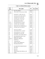
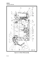
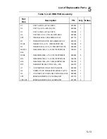
Страница 102: ...8062A Instruction Manual 5 12 8062A 4031 iv39c eps Figure 5 2 A1 Main PCB Assembly...
Страница 106: ...8062A Instruction Manual 6 2...
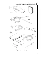
Страница 108: ...8062A Instruction Manual 6 4 dy55c eps Figure 6 1 Accessories...
Страница 109: ...Accessory Information Temperature Probes 80T 150C and 80T 150F 6 6 5 dy56c eps Figure 6 1 Accessories cont...
Страница 118: ...8062A Instruction Manual 7 2...
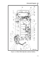
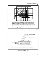
Страница 119: ...Schematic Diagrams 7 7 3 8062A 4031 iv39c eps Figure 7 1 A1 Main PCB Component Locations TopView...
Страница 122: ...8062A Instruction Manual 7 6...
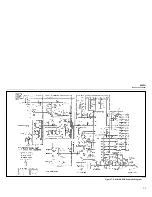
Страница 123: ...8062A Instruction Manual 7 7 8062A 1201 iu46c eps Figure 7 5 A1 Main PCB Schmatic Diagram...
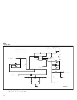
Страница 124: ...8062A Instruction Manual 7 8 8060A 1003 iu61f eps Figure 7 6 A3 RMS PCB Schmatic Diagram...


