


8062A
Instruction Manual
4-10
•
The LCD interconnect (item 7) and the microcomputer interconnect
(item 5) should not be touched with fingers or contaminated. Handle
these items with tweezers and keep them clean.
•
The microcomputer interconnect (item 7) is susceptible to corrosion
caused by the reaction between the metal in the connector and possible
contaminates in the air such as smoke or sulfur. Store the connector in
an air-tight container if the LCD is disassembled for a long period of
time.
•
Do not get fingerprints or dirt on the LCD display, the display lens, or
the gasket.
•
While the LCD and microcomputer pcb are assembled, take care not to
press down on the display lens because pressure could damage the LCD.
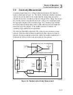
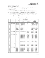
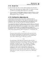
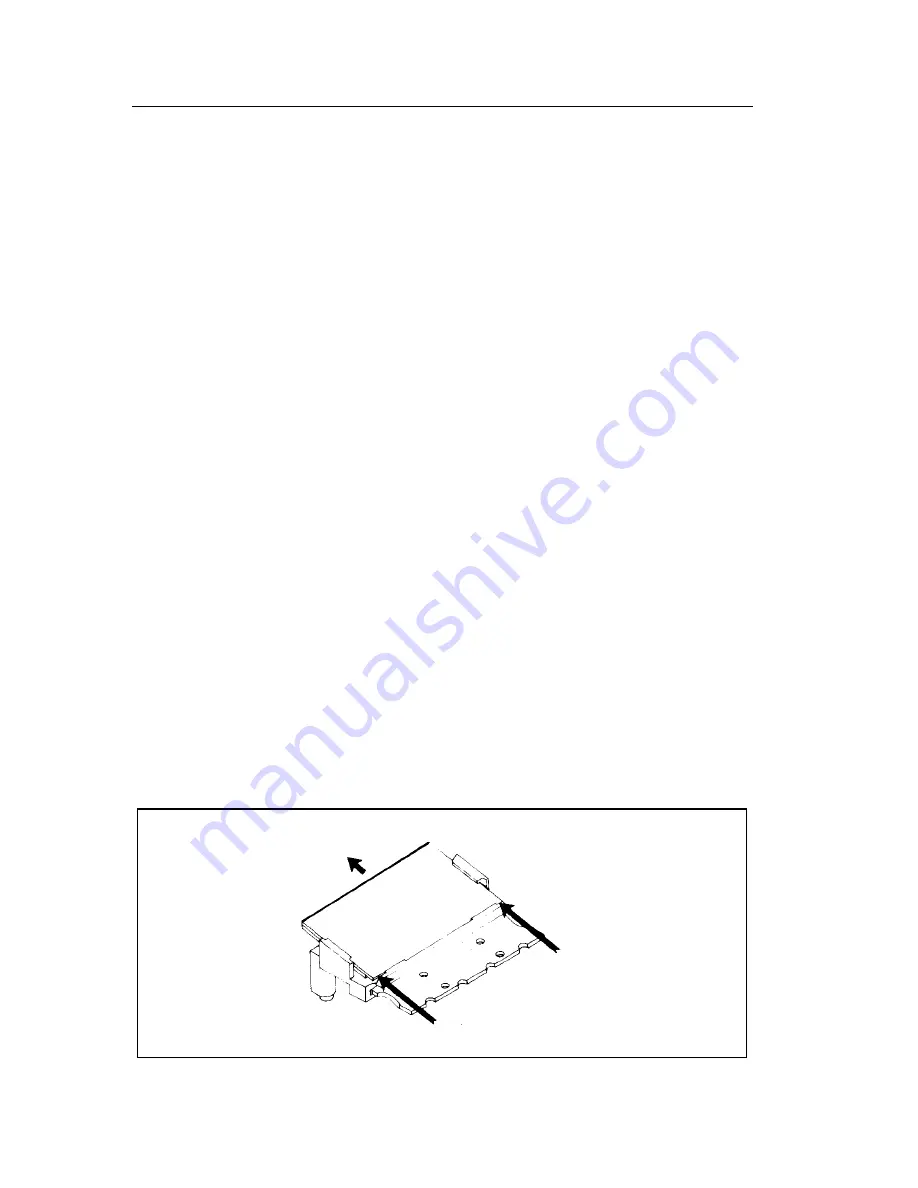
To disassemble the LCD, use your thumbnails and push on the corners of the
LCD display, gasket, and display lens so that all three components slide out
together as shown in Figure 4-3.
Note
It is not necessary to remove the main pcb from the bottom case to
disassemble or reassemble the LCD.
To assemble the LCD, use the following procedure:
1.
Align the LCD display (item 8) as indicated in Figure 4-2 and slide it
into place. The bottom edge of the LCD display should compress the
LCD interconnect (item 7) and slide underneath the two plastic notches
on the LCD bracket (item 1).
2.
Refer to Figure 4-2 and follow steps 9 and 10 to complete assembly.
Push corners with thumbnails.
Slide Out
dy34c.eps
Figure 4-3. Disassembling the LCD
Содержание 8062A
Страница 4: ......
Страница 8: ...8062A Instruction Manual iv...
Страница 10: ...8062A Instruction Manual vi...
Страница 12: ...8062A Instruction Manual viii 7 5 A1 Main PCB Schematic Diagram 7 7 7 6 A3 RMS PCB Schematic Diagram 7 8...
Страница 13: ...1 1 Chapter 1 Introduction and Specifications Contents Page 1 1 Introduction 1 3 1 2 Specifications 1 4...
Страница 14: ...8062A Instruction Manual 1 2...
Страница 24: ...8062A Instruction Manual 2 2...
Страница 50: ...8062A Instruction Manual 2 28...
Страница 52: ...8062A Instruction Manual 3 2...
Страница 62: ...8062A Instruction Manual 3 12...
Страница 64: ...8062A Instruction Manual 4 2...
Страница 90: ...8062A Instruction Manual 4 28...
Страница 92: ...8062A Instruction Manual 5 2...
Страница 97: ...List of Replaceable Parts 5 5 7 Test Button Up 1 of 2 dy37c eps Figure 5 1 8062A Final Assembly...
Страница 98: ...8062A Instruction Manual 5 8 Test Button Up 2 of 2 dy38c eps Figure 5 1 8062A Final Assembly cont...
Страница 102: ...8062A Instruction Manual 5 12 8062A 4031 iv39c eps Figure 5 2 A1 Main PCB Assembly...
Страница 106: ...8062A Instruction Manual 6 2...
Страница 108: ...8062A Instruction Manual 6 4 dy55c eps Figure 6 1 Accessories...
Страница 109: ...Accessory Information Temperature Probes 80T 150C and 80T 150F 6 6 5 dy56c eps Figure 6 1 Accessories cont...
Страница 118: ...8062A Instruction Manual 7 2...
Страница 119: ...Schematic Diagrams 7 7 3 8062A 4031 iv39c eps Figure 7 1 A1 Main PCB Component Locations TopView...
Страница 122: ...8062A Instruction Manual 7 6...
Страница 123: ...8062A Instruction Manual 7 7 8062A 1201 iu46c eps Figure 7 5 A1 Main PCB Schmatic Diagram...
Страница 124: ...8062A Instruction Manual 7 8 8060A 1003 iu61f eps Figure 7 6 A3 RMS PCB Schmatic Diagram...


