


Operation Instructions
Operation
2
2-19
Resistance measurements for all ranges are made using a two-wire
ratiometric technique. This means that test lead resistance may affect the
accuracy in the 200
Ω
range. You can correct this error by shorting the test
leads together, reading the test lead resistance, and then subtracting it from
resistance readings. The most convenient way to do this is with the relative
function as described later in this chapter. This technique is also useful for
removing the .02
Ω
error factor in the 200
Ω
range (refer to resistance
specifications in Chapter 1).
2-18. Autoranging Megohms
When the autoranging M
Ω
range is selected, the 8062A automatically selects
the range appropriate for the measurement. The measurement resolution
decreases in the two higher M
Ω
ranges as shown in Table 2-3. Readings
made at the crossover points between ranges are microcomputer-stabilized
by an offset in the upscale and downscale directions. Range changes are
made at 2.00 M
Ω
and 20.00 M
Ω
as readings go upscale, or at 19.0 M
Ω
and
1.90 M
Ω
as readings go downscale.
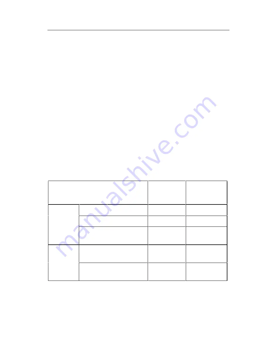
Table 2-3. Resistance Function Autoranges and Resolution
Range
Resolution
No. of Digits
Possible in
Reading
2 M
Ω
100
Ω
4½
M
Ω
20 M
Ω
10 k
Ω
3½
Autorange
300 M
Ω
20 to 99.9 M
Ω
100 to 300 M
Ω
100 k
Ω
1 M
Ω
3
3
k
Ω
2 k
Ω
20 k
Ω
0.1
Ω
10
Ω
4½
3½
Autorange
300 k
Ω
20 to 99.9 k
Ω
100 to 299 k
Ω
100
Ω
1 k
Ω
3
3
Содержание 8062A
Страница 4: ......
Страница 8: ...8062A Instruction Manual iv...
Страница 10: ...8062A Instruction Manual vi...
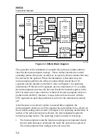
Страница 12: ...8062A Instruction Manual viii 7 5 A1 Main PCB Schematic Diagram 7 7 7 6 A3 RMS PCB Schematic Diagram 7 8...
Страница 13: ...1 1 Chapter 1 Introduction and Specifications Contents Page 1 1 Introduction 1 3 1 2 Specifications 1 4...
Страница 14: ...8062A Instruction Manual 1 2...
Страница 24: ...8062A Instruction Manual 2 2...
Страница 50: ...8062A Instruction Manual 2 28...
Страница 52: ...8062A Instruction Manual 3 2...
Страница 62: ...8062A Instruction Manual 3 12...
Страница 64: ...8062A Instruction Manual 4 2...
Страница 90: ...8062A Instruction Manual 4 28...
Страница 92: ...8062A Instruction Manual 5 2...
Страница 97: ...List of Replaceable Parts 5 5 7 Test Button Up 1 of 2 dy37c eps Figure 5 1 8062A Final Assembly...
Страница 98: ...8062A Instruction Manual 5 8 Test Button Up 2 of 2 dy38c eps Figure 5 1 8062A Final Assembly cont...
Страница 102: ...8062A Instruction Manual 5 12 8062A 4031 iv39c eps Figure 5 2 A1 Main PCB Assembly...
Страница 106: ...8062A Instruction Manual 6 2...
Страница 108: ...8062A Instruction Manual 6 4 dy55c eps Figure 6 1 Accessories...
Страница 109: ...Accessory Information Temperature Probes 80T 150C and 80T 150F 6 6 5 dy56c eps Figure 6 1 Accessories cont...
Страница 118: ...8062A Instruction Manual 7 2...
Страница 119: ...Schematic Diagrams 7 7 3 8062A 4031 iv39c eps Figure 7 1 A1 Main PCB Component Locations TopView...
Страница 122: ...8062A Instruction Manual 7 6...
Страница 123: ...8062A Instruction Manual 7 7 8062A 1201 iu46c eps Figure 7 5 A1 Main PCB Schmatic Diagram...
Страница 124: ...8062A Instruction Manual 7 8 8060A 1003 iu61f eps Figure 7 6 A3 RMS PCB Schmatic Diagram...


