


8062A
Instruction Manual
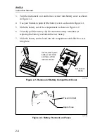
2-8
Table 2-1. Controls, Indicators and Connectors (cont)
Item
No.
Name
Function
10
Tilt Bail
A fold-out stand. The bail may also be
removed (press on one of the legs at the
hinge of the bail) and reinserted from the top
as a hook for hanging the instrument.
11
Power Switch
Slide switch for turning instrument on or off.
12
Display
4½ digit LCD display (19999 maximum) with
decimal point, minus sign, over-range,
continuity and relative indicators.
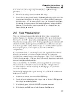
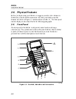
2-7. Display
The 8062A provides measurement results on the 4-1/2 digit LCD display
(refer to Figure 2-4 or your instrument). The decimal point is placed
automatically. Symbols in the upper portion of the display indicate when one
of the secondary functions is enabled. The measurement units are indicated
by the range switch that is pushed in. Leading zeroes not displayed.
Relative
Function
in Use
Audible
Continuity
Enabled
Visible Continuity
Enabled
Low Battery
Indicator
Continuity
Indicator
dy06f.eps
Figure 2-4. 8062A Display
If you are taking a measurement and the OL symbol appears on the display
(Figure 2-5), an overrange condition is indicated, meaning that the input is
higher than the range selected. You should select a higher range for the
measurement. The OL symbol does not necessarily mean that the instrument
is being exposed to a damaging input condition. For example, when
measuring resistance, an open input will cause OL to appear.
Содержание 8062A
Страница 4: ......
Страница 8: ...8062A Instruction Manual iv...
Страница 10: ...8062A Instruction Manual vi...
Страница 12: ...8062A Instruction Manual viii 7 5 A1 Main PCB Schematic Diagram 7 7 7 6 A3 RMS PCB Schematic Diagram 7 8...
Страница 13: ...1 1 Chapter 1 Introduction and Specifications Contents Page 1 1 Introduction 1 3 1 2 Specifications 1 4...
Страница 14: ...8062A Instruction Manual 1 2...
Страница 24: ...8062A Instruction Manual 2 2...
Страница 50: ...8062A Instruction Manual 2 28...
Страница 52: ...8062A Instruction Manual 3 2...
Страница 62: ...8062A Instruction Manual 3 12...
Страница 64: ...8062A Instruction Manual 4 2...
Страница 90: ...8062A Instruction Manual 4 28...
Страница 92: ...8062A Instruction Manual 5 2...
Страница 97: ...List of Replaceable Parts 5 5 7 Test Button Up 1 of 2 dy37c eps Figure 5 1 8062A Final Assembly...
Страница 98: ...8062A Instruction Manual 5 8 Test Button Up 2 of 2 dy38c eps Figure 5 1 8062A Final Assembly cont...
Страница 102: ...8062A Instruction Manual 5 12 8062A 4031 iv39c eps Figure 5 2 A1 Main PCB Assembly...
Страница 106: ...8062A Instruction Manual 6 2...
Страница 108: ...8062A Instruction Manual 6 4 dy55c eps Figure 6 1 Accessories...
Страница 109: ...Accessory Information Temperature Probes 80T 150C and 80T 150F 6 6 5 dy56c eps Figure 6 1 Accessories cont...
Страница 118: ...8062A Instruction Manual 7 2...
Страница 119: ...Schematic Diagrams 7 7 3 8062A 4031 iv39c eps Figure 7 1 A1 Main PCB Component Locations TopView...
Страница 122: ...8062A Instruction Manual 7 6...
Страница 123: ...8062A Instruction Manual 7 7 8062A 1201 iu46c eps Figure 7 5 A1 Main PCB Schmatic Diagram...
Страница 124: ...8062A Instruction Manual 7 8 8060A 1003 iu61f eps Figure 7 6 A3 RMS PCB Schmatic Diagram...


